Cover for machine tool guide structures

a technology for machine tools and guide structures, applied in the direction of maintenance and safety accessories, mechanical control devices, building components, etc., can solve the problems of affecting the use of machine tools

Inactive Publication Date: 2007-10-04
GEBR HELLER MASCHFAB GMBH
View PDF6 Cites 23 Cited by
  • Summary
  • Abstract
  • Description
  • Claims
  • Application Information

AI Technical Summary

Benefits of technology

[0013]The present invention provides a cover arrangement for a machine tool for covering guide and drive structures, comprising a pleated wall arrangement which can be expanded and compressed upon movement of a carriage between which and a machine wall it is connected. The pleated wall structure is provided with armor

Problems solved by technology

A corresponding space is often not available in modern machinery.
It includes two pleated wall arrangements interconnected by web walls which also results in a relatively thick, space consuming structure.
Cover arrangements for machine tools encounter various problems.
If they fail, the machine tool becomes inoperative.
If, with the usual

Method used


Image

  • Cover for machine tool guide structures
  • Cover for machine tool guide structures
  • Cover for machine tool guide structures

Examples


Embodiment Construction

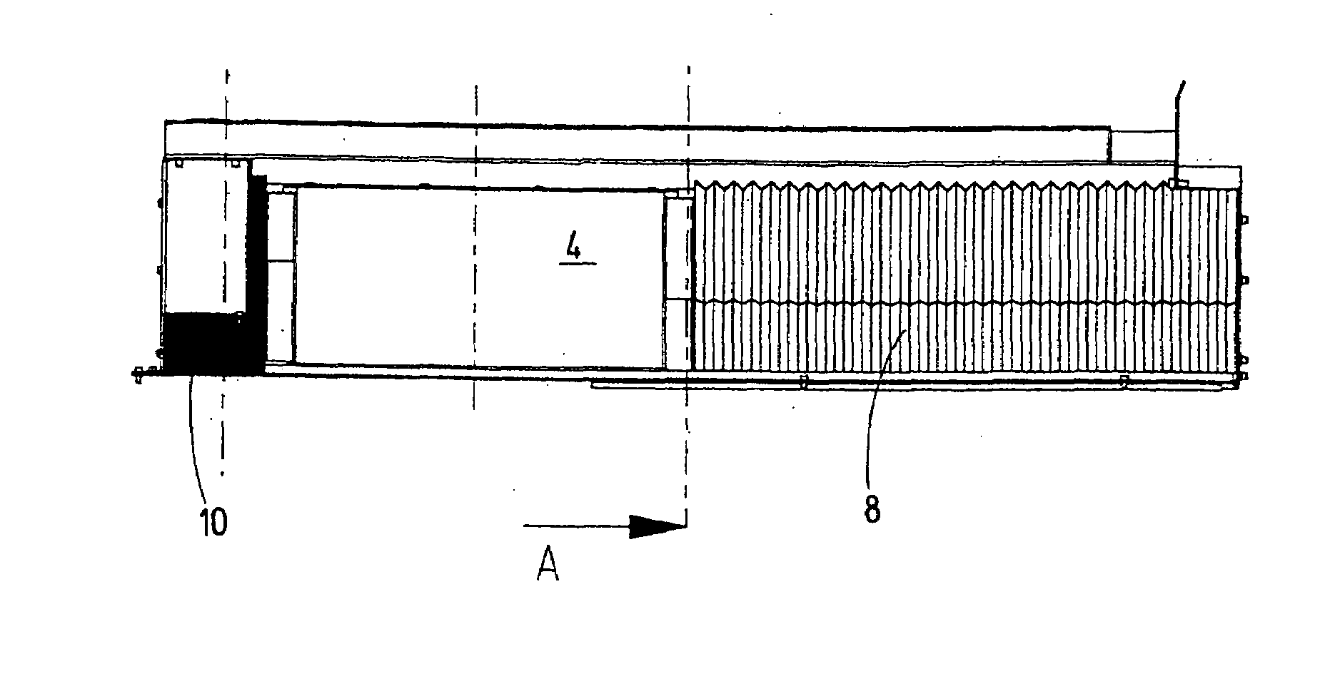
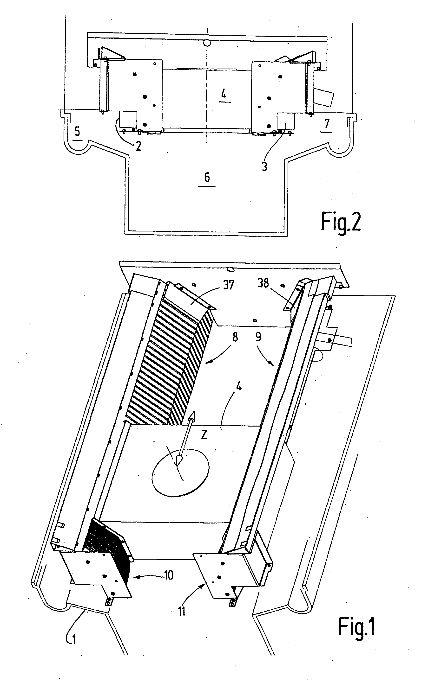
[0032]FIGS. 1 and 2 show, as a component of a machine tool, a machine bed 1 provided with two guide structures 2, 3, shown schematically in FIG. 2. A carriage 4 is supported by the guide structures so as to be movable in the working space of the machine tool. Below the guide structures 2, 3 collections spaces 5, 6 and 7 are provided for the collection of chips and their removal from the machine.

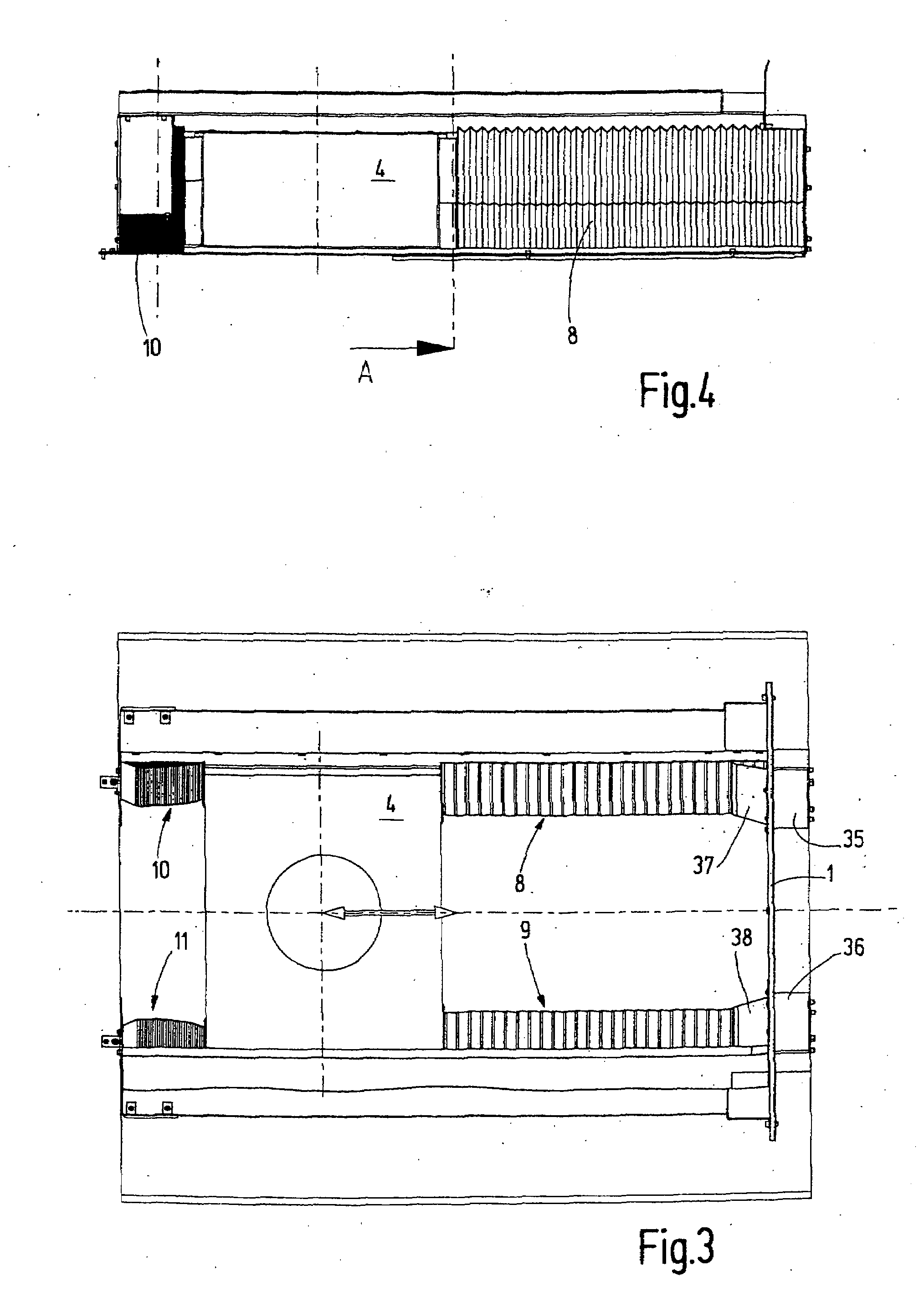
[0033]For the protection of the guide structures 2, 3 from chips, cover arrangements 8, 9, 10, 11 are provided as shown in FIGS. 3 and 4, each being connected with one end to the carriage 4 and the other end to the machine bed 1 or a stationary part thereof. The cover arrangements 8, 9 are arranged mirror-reversed with respect to the vertical center plane of the machine tool.

[0034]The cover arrangements 8 to 11 are telescoping in the direction of movement of the carriage 4, that is, as shown in FIG. 1, for example, in the Z direction. In this way, they permit uninhibited movement of the carri...


PUM


Abstract

In a cover arrangement for a machine tool for covering guide and drive structures, comprising a pleated wall arrangement which can be expanded and compressed upon movement of a carriage between which and a machine wall it is connected. The pleated wall structures is provided with armor lamellas which are anchored to the pleat sections of the wall structures and over-lap for covering the pleated wall structure which is movably supported on guide tracks which are disposed in planes extending at an obtuse angle facilitating installation and removal of the cover arrangement.

Description

CROSS-REFERENCE TO RELATED APPLICATION[0001]This application claims the priority benefits of German Application No. 10 2006 015 799.0-14 filed Apr. 3, 2006.BACKGROUND OF THE INVENTION[0002]This invention relates to a cover for a machine tool, particularly for covering guide structures and / or drives.[0003]Machine tools include, for example, movably supported carriages for supporting a workpiece or a device for holding a workpiece or a carriage supporting one or more machining spindles. The respective carriage is supported, for example, on a machine frame by means of linear guide structures which need to be protected from dirt and dust.[0004]To this end, German patent, DE 102 23 044 A1 discloses self-supporting bellows structure with U-shaped bent metal sheets, which are interconnected by pleat structures. The U-shaped metal sheets form an armor for the protection of the pleated wall structure. The legs of a U-shaped metal sheet accommodate there between the respective adjacent U-shap...

Claims


Application Information

Patent Timeline
IPC IPC(8): F16C33/00
CPCB23Q11/0816Y10T74/219Y10T74/2193B23Q11/0825B23Q2011/0808
Inventor SCHIRLING, MICHAEL
Owner GEBR HELLER MASCHFAB GMBH
Why Eureka
Try Eureka