Impeller for fuel pump and fuel pump in which the impeller is employed

a technology of impeller and fuel pump, which is applied in the direction of liquid fuel engines, machines/engines, liquid fuel feeders, etc., can solve the problems and achieve the effect of restricting a decrease in pump efficiency and reducing the peak of a sound pressure of a nois

Inactive Publication Date: 2007-10-04
DENSO CORP
View PDF18 Cites 4 Cited by
  • Summary
  • Abstract
  • Description
  • Claims
  • Application Information

AI Technical Summary

Benefits of technology

[0009]The present invention addresses the above disadvantages. Thus, it is an objective of the present invention to provide an impeller for a fuel pump. The impeller reduces a peak of a sound pressure of a noise and restricts a decrease in pump efficiency. Furthermore, it is another objective to provide a fuel pump that employs the impeller.

Problems solved by technology

The impeller reduces a peak of a sound pressure of a noise and restricts a decrease in pump efficiency.

Method used


Image

  • Impeller for fuel pump and fuel pump in which the impeller is employed
  • Impeller for fuel pump and fuel pump in which the impeller is employed
  • Impeller for fuel pump and fuel pump in which the impeller is employed

Examples


first embodiment

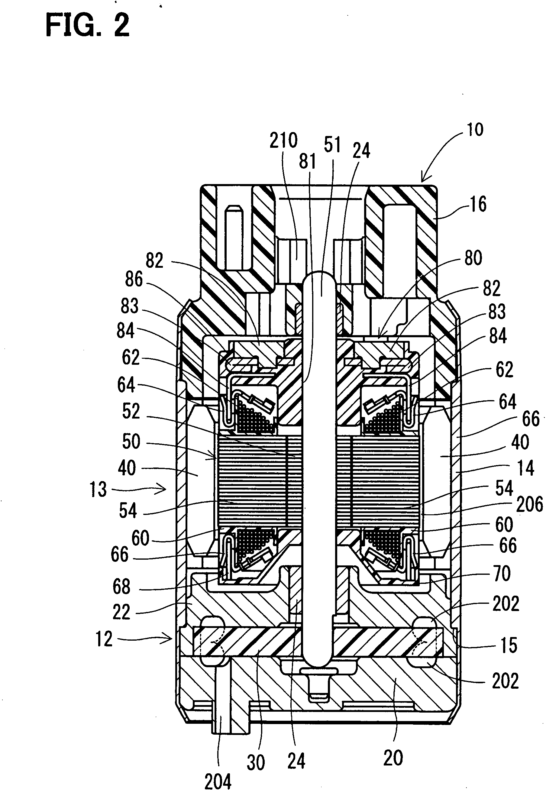
[0025]FIG. 2 shows a fuel pump 10, in which an impeller 30 according to a first embodiment of the present invention is employed. The fuel pump 10 is, for example, an in-tank turbine pump, which is attached to an inside of a fuel tank of a vehicle or the like. The fuel pump 10 supplies fuel in the fuel tank to a fuel injection valve (not shown). The fuel pump 10 is set such that its discharge pressure includes a range of 0.25 to 1 [Mpa], its discharge rate includes a range of 50 to 250 [L / h], and its rotational speed includes a range of 4000 to 12000 [rpm].

[0026]The fuel pump 10 includes a pump unit 12 and a motor unit 13, which drives the pump unit 12 to rotate. A housing 14 is for the pump unit 12 and the motor unit 13, and caulks an end cover 16 and a pump case 20.

[0027]The pump unit 12 is a turbine pump, which has the pump case 20, a pump case 22 and the impeller 30. The pump case 22 is press-fitted into the housing 14, and is pressed on a stage part 15 of the housing 14 in an ax...

second embodiment

[0048]FIG. 7 shows a second embodiment of the present invention. The same numerals are used to indicate substantially the same components as the first embodiment described above. In the second embodiment, a configuration of a fuel pump, in which an impeller 90 is employed, is substantially the same as the first embodiment.

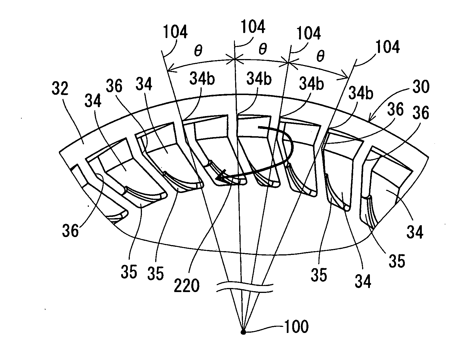
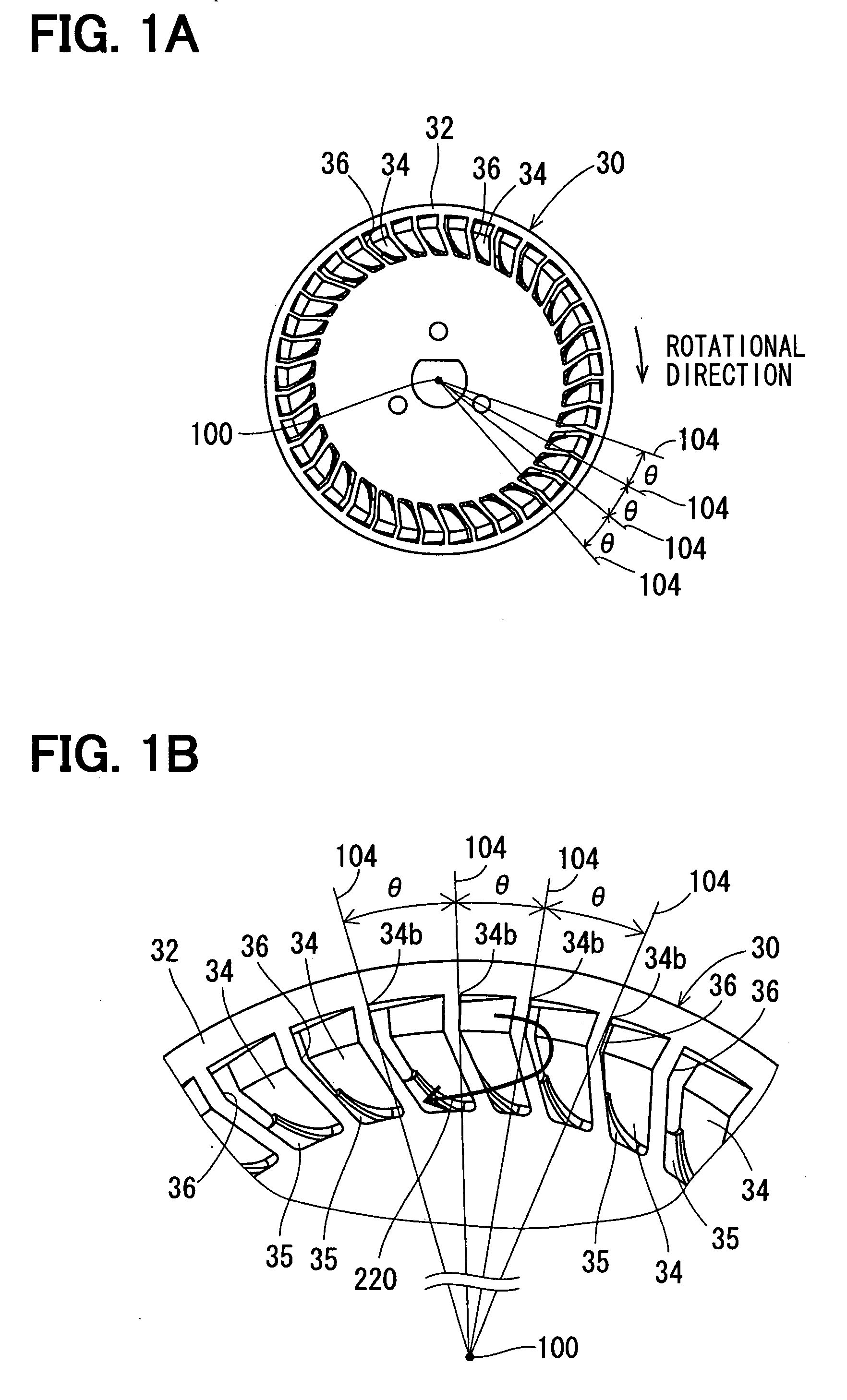
[0049]In the impeller 30 of the first embodiment, the radially outer part of the vane grooves 36 is surrounded by the annular part 32. In the impeller 90 of the second embodiment, on the other hand, radially outer parts of vane grooves 92 is open. Two vane grooves 92 adjacent to each other in a rotational direction of the impeller 90 are divided by a vane 94.

[0050]In the second embodiment as well, adjacent vane angles θ of the vanes 94 and their dispersion range are set in a range of 8°≦adjacent vane angle≦12°, and 2.5°≦dispersion range≦4°, respectively.

Other Embodiments

[0051]Although the dispersion range and the adjacent vane angle θ are set in the range of 2.5°≦d...


PUM


Abstract

An impeller is employed for a fuel pump and boosts a pressure of fuel by rotating the fuel in a pump passage formed in the fuel pump in a rotational direction of the impeller. The impeller includes a plurality of vane grooves formed adjacent to each other in the rotational direction of the impeller and a plurality of vanes formed adjacent to each other in the rotational direction. Each one of the plurality of vanes divides one of adjacent two of the plurality of vane grooves from the other. A difference between a maximal value and a minimum value of an adjacent vane angle is set in a range of 2.5° to 4°. A fuel pump includes a motor unit, the impeller, and a casing member. The impeller is rotated by rotation driving force of the motor unit. The casing member rotatably receives the impeller and defines the pump passage.

Description

CROSS REFERENCE TO RELATED APPLICATION[0001]This application is based on and incorporates herein by reference Japanese Patent Application No. 2006-95335 filed on Mar. 30, 2006.BACKGROUND OF THE INVENTION[0002]1. Field of the Invention[0003]The present invention relates to an impeller for a fuel pump and a fuel pump in which the impeller is employed.[0004]2. Description of Related Art[0005]In a conventional fuel pump, a plurality of vane grooves is formed on a disklike impeller in its rotational direction, and a vane divides vane grooves that are adjacent to each other in a rotational direction of the impeller. By rotating the impeller, a pressure of fuel in a pump passage formed along the vane grooves is boosted (e.g., JP11-50990A corresponding to U.S. Pat. No. 5,975,843). In such a fuel pump, if vanes adjacent to each other in the rotational direction of the impeller are arranged at equiangular intervals, a noise having a high peak of a sound pressure at a frequency that correspond...

Claims


Application Information

Patent Timeline
Patent Type & Authority Applications(United States)
IPC IPC(8): F04D5/00
CPCF04D29/188F02M37/08F04D5/00
Inventor NARISAKO, HIDEKIHAZAMA, TADASHIOI, KIYOTOSHIEBIHARA, YOSHIO
Owner DENSO CORP
Why Eureka
Try Eureka