Steering apparatus

a steering apparatus and steering shaft technology, applied in the direction of underwater vessels, non-deflectable wheel steering, special data processing applications, etc., can solve the problems of reducing the flexibility of mounting layout, reducing the mounting ability of the motor on the vehicle body, and increasing the size of the steering assisting motor, so as to reduce the peaks of switching noise

Inactive Publication Date: 2006-12-26
HONDA MOTOR CO LTD
View PDF29 Cites 21 Cited by
  • Summary
  • Abstract
  • Description
  • Claims
  • Application Information

AI Technical Summary

Benefits of technology

[0007]In view of the foregoing prior art problems, it is an object of the present invention to provide a steering apparatus including two motor drive circuits which can effectively reduce unwanted switching noise and magnetostrictive sound that would be produced by driving of a steering assisting motor through great current switching at high speed.
[0009]With the arrangement that the control frequency, at which the switching element is switched on and off, is controlled to differ between the two motor drive circuits, the PWM switching of the switching elements of the motor drive circuits can be prevented from occurring at the same timing. As a consequence, the present invention can effectively reduce the peaks of the switching noise levels by virtue of level distribution attained by the differentiated switching timing of the switching elements.
[0011]With the arrangement that the phase of the pulse signal for switching on and off the switching element is caused to differ between the motor drive circuits, the PWM switching of the switching elements of the motor drive circuits can be prevented from occurring at the same timing. As a consequence, the present invention can effectively reduce the peaks of the switching noise levels by virtue of level distribution attained by the differentiated switching timing of the switching elements.

Problems solved by technology

Therefore, the size of the steering assisting motor tends to increase, and the increased size would result in lowered flexibility in a mounting layout (lowered mountability) of the motor on the vehicle body.
Further, such large-sized vehicles require a non-standardized, dedicated steering assisting motor and a motor control drive section therefor, which would result in increased manufacturing costs.
However, such electric power steering apparatus redundantly including two motor drive circuits would present the following inconveniences.
It is ordinary today to control the steering assisting motor by means of a PWM (Pulse Width Modulation) control scheme using FETs of the motor drive circuit as switching elements, which would however produce greater switching noise and magnetostrictive sound as the current input to the switching elements and the switching speed of the switching elements increase.
The greater switching noise and magnetostrictive sound would lower the merchantability of vehicles equipped with the electric power steering apparatus.
Thus, in the case of the electric power steering apparatus with two motor drive circuits, adverse influences of the switching noise and magnetostrictive sound resulting from the PWM control would become more significant because each of the two motor drive circuits produces such switching noise and magnetostrictive sound.
These inconveniences commonly occur in steering apparatus including two motor drive circuits, irrespective of whether the steering assisting motors are of the brushless type or brushed type.

Method used


Image

  • Steering apparatus
  • Steering apparatus
  • Steering apparatus

Examples


first embodiment

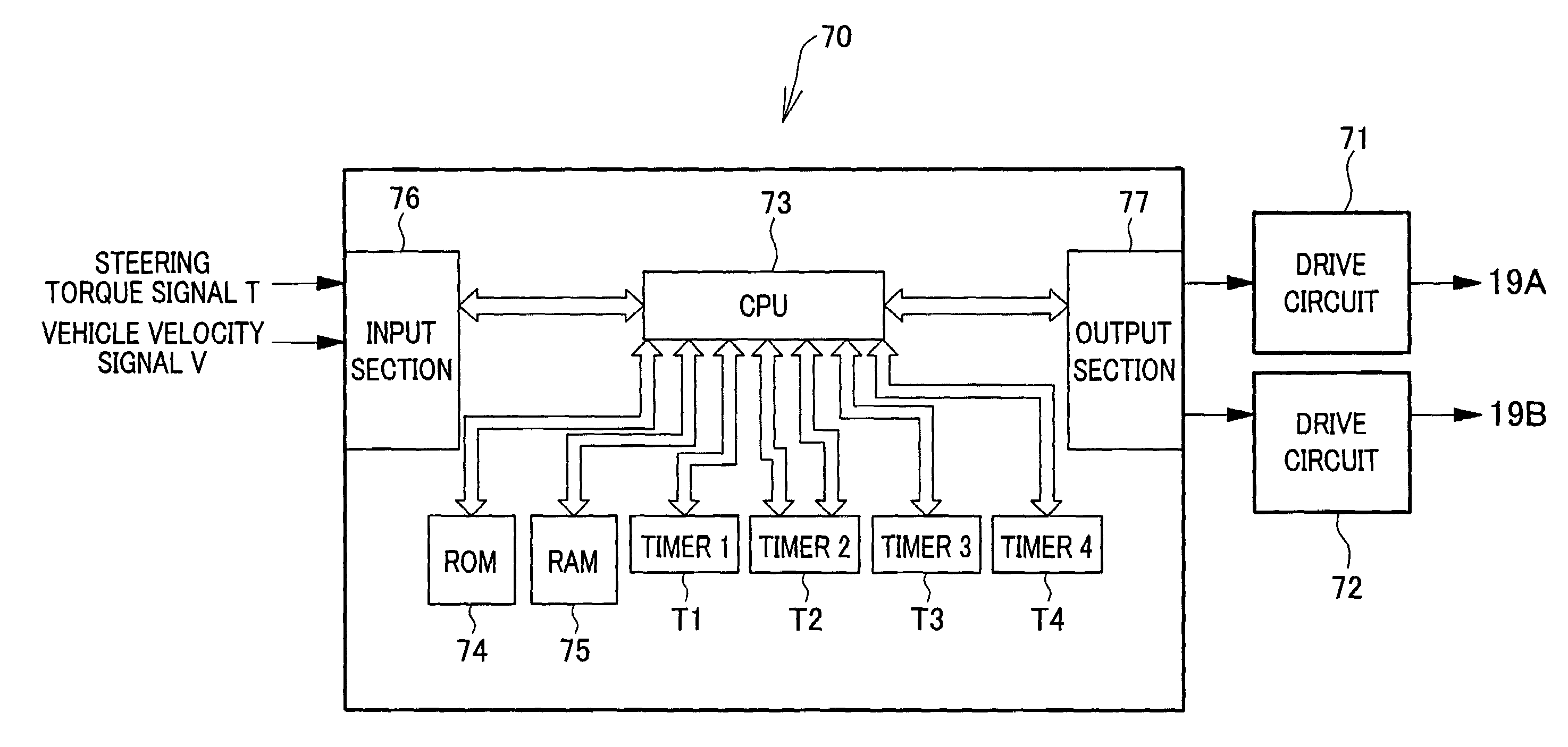
[0047]The following paragraphs describe characteristic arrangements of the first embodiment, with reference to FIGS. 4 and 5 and FIGS. 6 and 7. FIG. 6 shows the microcomputer 70 of the controller device in the case where there are provided a single ECU and two motor drive circuits, and FIG. 7 shows the microcomputers 80 and 90 in the case where there are provided two ECUs and two motor drive circuits.

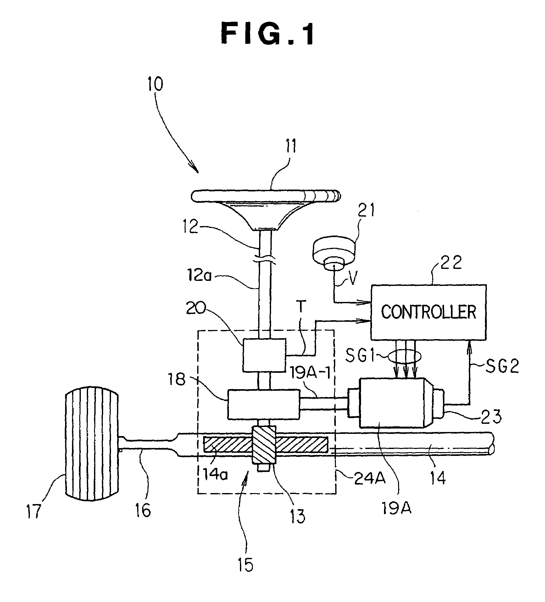
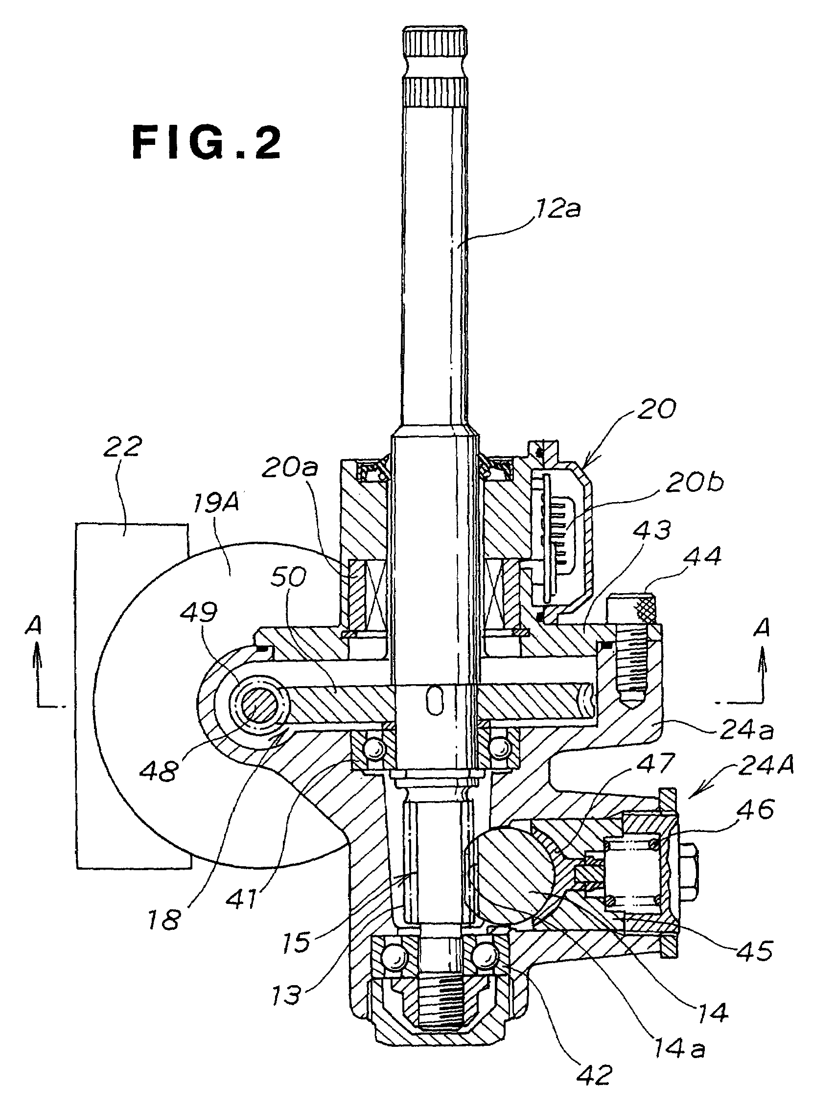
[0048]As illustrated in FIGS. 4 and 5, the gearboxes 24A and 24B are provided on two axially-spaced-apart portions of the rack shaft 14. The first gearbox 24A connects to the pinion shaft 12a of the steering shaft 12, and the second gearbox 24B has the second motor 19B attached thereto in the dual-motor-type electric power steering apparatus 10. Specifically, the motors 19A and 19B are attached to the first and second gearboxes 24A and 24B, respectively, via the power transmission mechanisms 18. Steering assisting torque, produced by rotation of the two motors 19A and 19B, is applied to...

second embodiment

[0069]The following paragraphs describe the invention in relation to the case where the steering assisting motors 19A and 19B are of the brushed type. In this case, the controller device 22 is similar in construction to that employed for the brushless motors, and thus the controller device 22 for the brushed motors 19A and 19B are also described with reference to FIGS. 6 and 7 having been explained above in relation to the brushless motors.

[0070]Here, the timers T1 and T3 for setting the cyclic periods of the PWM control pulses are set to the same settings, with either one of the timers T1 or T3 being imparted with a phase offset. For example, both of the timers T1 and T3 are set to provide a 20 kHz frequency of the PWM control, with the timer T3 being imparted with a phase offset. In other words, the timers T1 and T3 are set to provide the same frequency, but different phases, of the PWM control signals, so as to prevent the respective switching elements of the drive circuits from ...

third embodiment

[0075]Next, the present invention will be described with reference to FIG. 10, in relation the a detailed construction of the controller device (ECU) 22 in the steering apparatus having redundant control arrangements.

[0076]As shown in the figure, detection signal output terminals of the steering torque detection section 20 comprise pairs of opposite end terminals 20a and 20b, and a pair of central terminals 20c. Two electrical connector sections 141a and 141b are provided between the opposite end terminals 20a, 20b and central terminals 20c and the controller device 22. Each of the connector sections 141a and 141b includes a wiring harness and coil connector. The controller device 22 includes torque signal input sections 142a and 142b provided in corresponding relation to the connector sections 141a and 141b.

[0077]Within the controller device 22, there are provided three CPUs (CPU 1-CPU 3) 143a, 143b and 143c. Two timers T100a, T101a, T100b, 1001b or T100c, 101c are provided for ea...


PUM


Abstract

Steering apparatus includes at least one motor for generating a steering assisting force in a direction to steer a steerable wheel, two drive circuits having respective switching elements for PWM-controlling the motor, and a controller for differentiating, between the drive circuits, a control frequency at which the switching element is switched on and off. The differentiated PWM switching timing can effectively reduce switching noise and magnetostrictive sound of the motor.

Description

FIELD OF THE INVENTION[0001]The present invention relates generally to steering apparatus, and more particularly to a steering apparatus including at least one steering assisting motor and two drive circuits for driving the motor.BACKGROUND OF THE INVENTION[0002]Among the conventionally-known steering apparatus are electric power steering apparatus and steer-by-wire steering systems. As well known, the electric power steering apparatus are steering assisting apparatus which are designed to activate an electric motor (steering assisting motor) as a human operator or driver manually operates the steering wheel, during driving of a motor vehicle, to thereby assist the driver's manual steering effort. In such electric power steering apparatus, the steering assisting motor, which provides a steering torque assist, is controlled by a motor control section (ECU), using a steering torque signal generated by a steering torque detection section detecting steering torque that is produced on th...

Claims


Application Information

Patent Timeline
Patent Type & Authority Patents(United States)
IPC IPC(8): G05B11/28B62D6/00B62D5/04B62D101/00B62D113/00B62D119/00H02K7/116
CPCB62D5/046H02K7/1166
Inventor ASAUMI, HISAOTSURUMIYA, OSAMUKITAZAWA, HIROKAZUSUTO, SHINJIYOSHIDA, JUNICHISUGANO, TOMOAKIMORISHITA, FUMIHIROHORII, HIROAKI
Owner HONDA MOTOR CO LTD
Why Eureka
Try Eureka