Hoist drum and rope pulley for fiber rope drives

a technology of fiber rope and rope pulley, which is applied in the field of rope drives, can solve the problems of high-strength fiber rope wear, the region in which the rope runs around the rope pulley is particularly susceptible to wear, and the predisposition to wear and the secure recognition of the discard state are problematic, so as to achieve the effect of reducing wear on high-strength fiber rope in particular

Active Publication Date: 2014-01-30
LIEBHERR COMPONENTS BIBERACH GMBH
View PDF36 Cites 23 Cited by
  • Summary
  • Abstract
  • Description
  • Claims
  • Application Information

AI Technical Summary

Benefits of technology

[0011]It is the underlying object of the present invention to provide an improved fiber rope drive, an improved hoist drum for such a fiber rope drive and / or an improved rope pulley for such a fiber rope drive which avoid the disadvantages of the prior art and advantageously further develop the latter. The wear on high-strength fiber ropes should in particular be reduced without impairing the winding quality.
[0013]It is therefore proposed to allow the cross-sectional change which occurs under transverse load at high-strength fiber ropes and to adapt the grooving of the hoist drum and / or of the rope pulley thereto and also not to even attempt to hold the rope in its ideal, typical circular cross-section by support. In accordance with the invention, the rope grooves have a pressed-flat, round groove contour which differs from the circular and which has a larger radius of curvature in the region of the groove base than in the region of the groove flanks adjacent thereto. In this respect, a departure is made from the previously customary path of supporting the rope, which is circular in cross-section before running onto the drum, by grooves of a circular contour on the hoist drum; the consideration rather forms the starting point that a fiber rope is no longer tensioned after running onto the hoist drum, but is also acted on by transverse forces and consequently an ovalization of the rope cross-section is adopted. The rope grooving is no longer adapted to the ideal, typically circular rope cross-section under a purely tensional load, but is rather adapted to the actual rope cross-section under tensile load and a transverse load on the hoist drum. A more uniform, better distributed pressure loading can hereby be achieved which can reduce the wear of the fiber rope.
[0017]To minimize the friction wear which occurs on the rope by the friction between the drum surface and the rope surface as a consequence of the rope stretching on the winding up onto the hoist drum, the grooving and / or the parts of the hoist drum contacting the rope is / are advantageously provided with a low-friction, preferably an approximately friction-free surface so that the rope can slide along the grooving surface or the guard plate surface free of wear. Such a low-friction surface can be achieved either by a very fine working of the surface, for example by polishing or grinding, and / or by a corresponding surface coating. Such a friction-reducing design of the rope-contacting drum surfaces generally also brings about considerable advantages without the aforesaid ovalized groove contour and can in particular, however, also be used in conjunction with the named ovalized groove contour. The rope-contacting surfaces of the hoist drum, in particular the grooving and the guard plate are advantageously finely-machined and / or surface-coated in the region of the deflector provided thereat such that the mean roughness depth Ra amounts to less than 1μm, preferably less than 0.35mμm, in particular approximately 0.15μm to 0.18 μm.
[0018]If the rope-contacting drum surface is provided with a friction-reducing surface coating in the aforesaid manner, a plastic coating can in particular be used. The surface coating is advantageously not only friction-reducing, but also damping in order to reduce peaks in the surface pressing and / or blows onto the rope running on.
[0022]In an advantageous further development of the invention, however, a grooving can only be provided with one pitch region and one parallel region, wherein the grooves are offset by around one full rope diameter in the named one pitch region, wherein here in turn the enlarged, ovalized rope diameter is also advantageously to be used as the basis again. Only one intersection region hereby results viewed over the drum circumference. This allows an inexpensive, good, multilayer rope coiling having a high wind quality and low rope wear.
[0023]To reduce the wear of the rope on the deflection into the next layer at the guard plates, a rope deflector having a preferably multistage deflection extent can be provided at at least one of the guard plates. Using such a rope deflector at the guard plate, it is avoided that the rope rises spirally at the guard plate and then drops abruptly onto the winding plane and it is instead insured that the rope is immediately guided into the next layer on reaching the guard plate. The rope deflector is in this respect arranged such that it deflects the rope back inwardly onto the next rope layer at the end of the drum rope groove or at the end of the rope layer, wherein the strength or thickness of this rope deflector can be based on the rope deflection angle on the drum, wherein a thicker rope deflector is provided with a smaller deflection angle than with larger deflection angles. Depending on the deflection angle, the thickness of the named rope deflector can lie in the range between 5% and 50% of the rope diameter.

Problems solved by technology

However, the predisposition to wear and the secure recognition of the discard state have been problematic with such high-strength fiber ropes up to now.
A smaller transverse compressive stiffness of the high-strength fiber ropes results from this which are substantially softer and thereby not as resistant to wear as steel ropes if the rope is wound onto a drum or runs over rope pulleys, which can result in much higher wear at the high-strength fiber ropes.
In this respect, the region in which the hoist rope is wound onto or off the hoist drum in one or more layers as well as the region in which the rope runs around a rope pulley are particularly susceptible to wear.
A similar behavior results with a multilayer winding, with here rope then sliding on rope, which likewise results in friction and wear.
The previously addressed problems of the increased rope wear on the use of high-strength fiber ropes, however, remains unsolved in these already known hoist drums.

Method used


Image

  • Hoist drum and rope pulley for fiber rope drives
  • Hoist drum and rope pulley for fiber rope drives
  • Hoist drum and rope pulley for fiber rope drives

Examples


Embodiment Construction

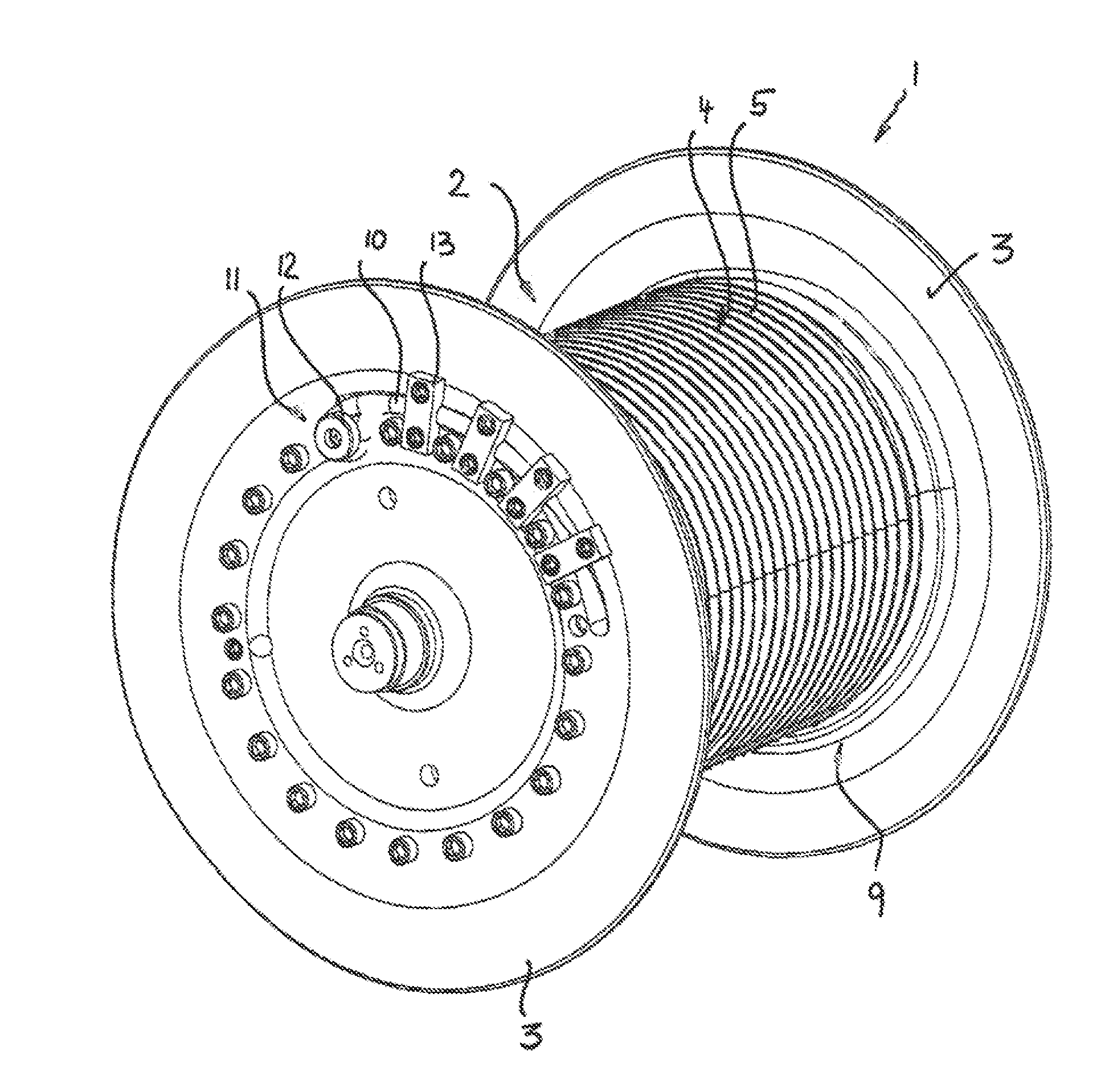
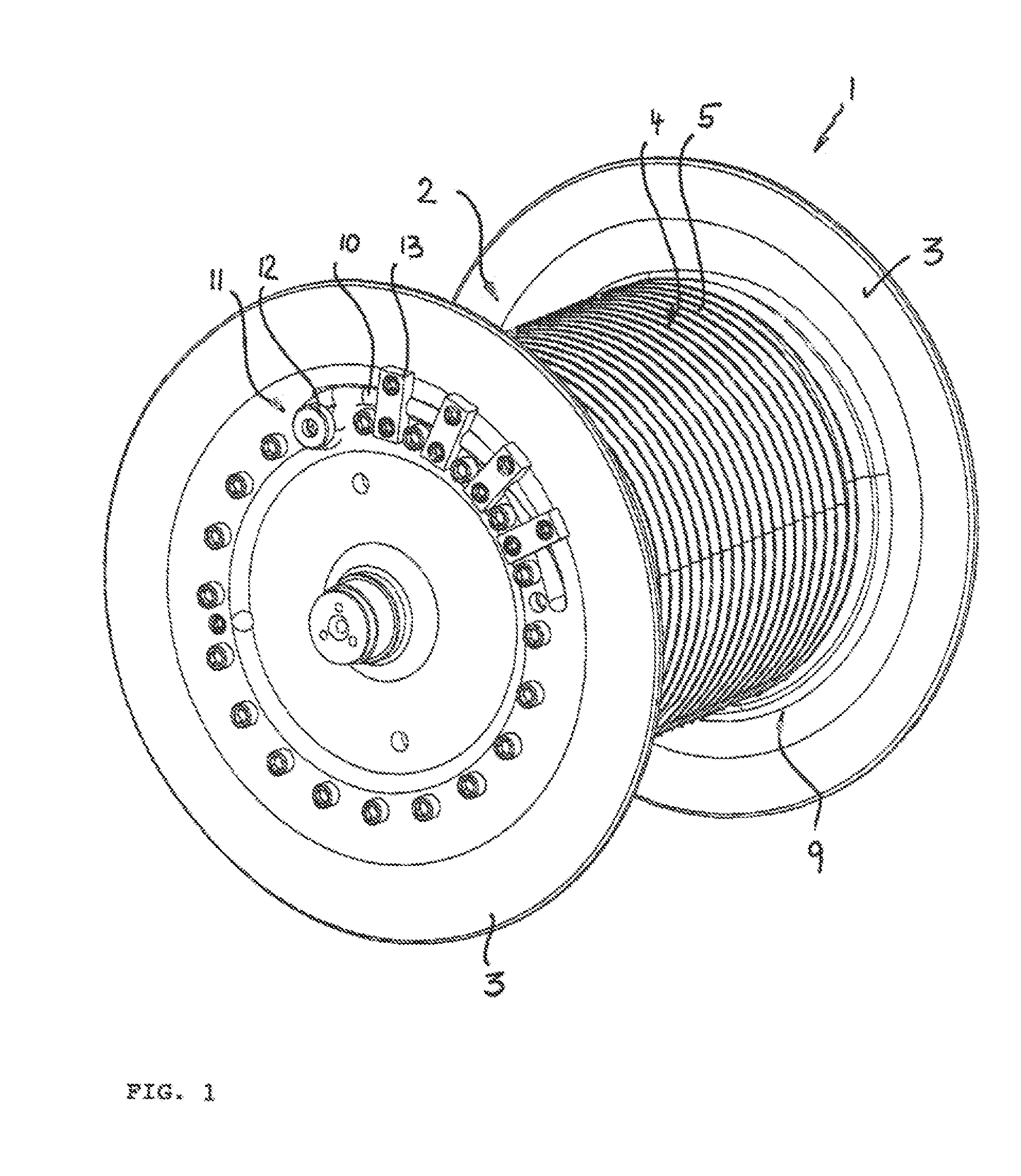
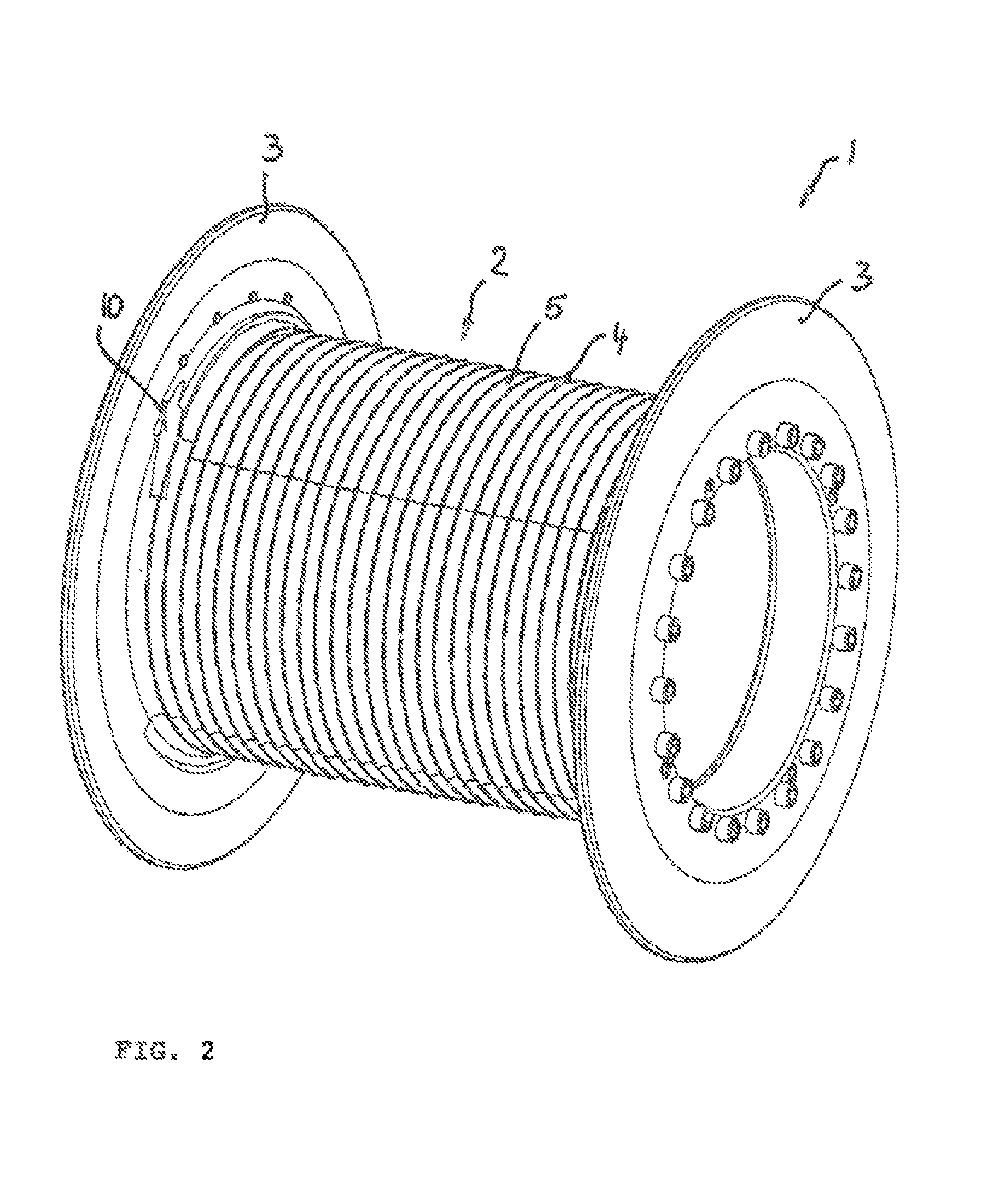
[0038]The hoist drum 1 shown in the Figures comprises an, in rough terms, cylindrical drum jacket body 2 to whose axial ends respective guard plates 3 are connected which, in rough terms, extend perpendicular to the longitudinal drum axis and project radially outwardly from the drum jacket surface and have a much larger diameter than the drum jacket.

[0039]The hoist drum 1 shown can in this respect in particular be used in the lifting gear of a crane such as a revolving tower crane or a mobile telescopic crane or a boom mast adjustment gear, but also in other hoist winches.

[0040]The named guard plates 3 can generally be connected in different manners to the drum jacket body 2. For example, a single-piece production would be conceivable, with advantageously, however, the guard plates 3 being able to be subsequently joined to the drum jacket body 2. In the drawn embodiment, the guard plates 3 are placed onto the drum jacket body 2 at the end face and are fastened using fastening means ...


PUM


Abstract

The present invention relates generally to rope drives working with high-strength fiber ropes such as crane hoists, boom adjustment gear, trolley traveling gear. etc. The invention in this respect in particular applies to hoist drums for the rope hoist winch of such a fiber rope drive having a drum jacket body which is provided with grooving at the peripheral side and having two guard plates adjacent to the drum jacket body at the end sides. The invention further relates to a rope pulley for such a fiber rope drive having a rotatably supported pulley body whose jacket surface has at least one rope groove. In accordance with the invention, the rope grooves have a flat-pressed, round groove contour which differs from the circular and which has a larger radius of curvature in the region of the groove base than in the region of the groove flanks adjacent thereto.

Description

CROSS-REFERENCE TO RELATED APPLICATIONS[0001]This application is a continuation of PCT Application No. PCT / EP2012 / 000312, filed 24 Jan. 2012, which claims priority to German Patent Application No. 20 2011 001 845.8, filed 24 Jan. 2011, both of which are incorporated herein in their entireties.BACKGROUND[0002]1. Technical Field[0003]The present invention relates generally to rope drives working with high-strength fiber ropes such as crane hoists, boom adjustment gear, trolley traveling gear, etc. The invention in this respect in particular applies to hoist drums for the rope hoist winch of such a fiber rope drive having a groove drum jacket body which is provided with grooving at the peripheral side and having two guard plates adjacent to the drum jacket body at the end sides. The invention further relates to a rope pulley for such a fiber rope drive having a rotatably supported pulley body whose jacket surface has at least one rope groove.[0004]2. Description of Related Art[0005]An ...

Claims


Application Information

Patent Timeline
Patent Type & Authority Applications(United States)
IPC IPC(8): B66D1/30B66D1/36
CPCB66D1/30B66D1/34B66D1/36F16H55/50
Inventor ILAKA, MUPENDEZERZA, HORST
Owner LIEBHERR COMPONENTS BIBERACH GMBH
Why Eureka
Try Eureka