
Self-closing medical staple

a medical staple and self-closing technology, applied in the field of medical staples, can solve the problems of increasing patient discomfort, causing pain in the lower leg, and increasing the cost of the procedur

Inactive Publication Date: 2007-10-04
MEDTRONIC VASCULAR INC
View PDF11 Cites 27 Cited by
  • Summary
  • Abstract
  • Description
  • Claims
  • Application Information

AI Technical Summary

Benefits of technology

[0005] According to one aspect of the disclosure, a medical staple is disclosed that includes two or more tines that are at least partially enclosed by an elastically deformable, or resilient body. The tines are movable with respect to each other between a closed configuration and a open configuration through elastic deformation of the resilient body.
[0006] According to another aspect of the disclosure, a method is provided for closing a wound. The method includes providing a staple including an elastically deformable, or resilient body that at least partially encloses the two or more tines. The method may further include moving the tines to an open

Problems solved by technology

The weight of the sandbag on the femoral artery may cause the lower leg to tingle or go numb.
The longer the recovery time, the more expensive the procedure becomes, the greater the patient discomfort, and the greater the risk of complications.
Medical stapling systems wherein the anvil remains external to the blood vessel are also known, but such systems may be difficult and expensive to make precisely in the small dimensions that are advantageous for blind closure of femoral arteriotomies.
Such all-metal, self-closing, medical staples and their associated delivery systems may also be difficult and expensive to make precisely in the small dimensions required.

Method used


Image

  • Self-closing medical staple
  • Self-closing medical staple
  • Self-closing medical staple

Examples


Embodiment Construction

[0020] Specific embodiments of the present disclosure are now described with reference to the figures. The terms “distal” and “proximal” are used in the following description with respect to a position or direction relative to the treating clinician. “Distal” or “distally” are a position distant from or in a direction away from the clinician. “Proximal” and “proximally” are a position near or in a direction toward the clinician.

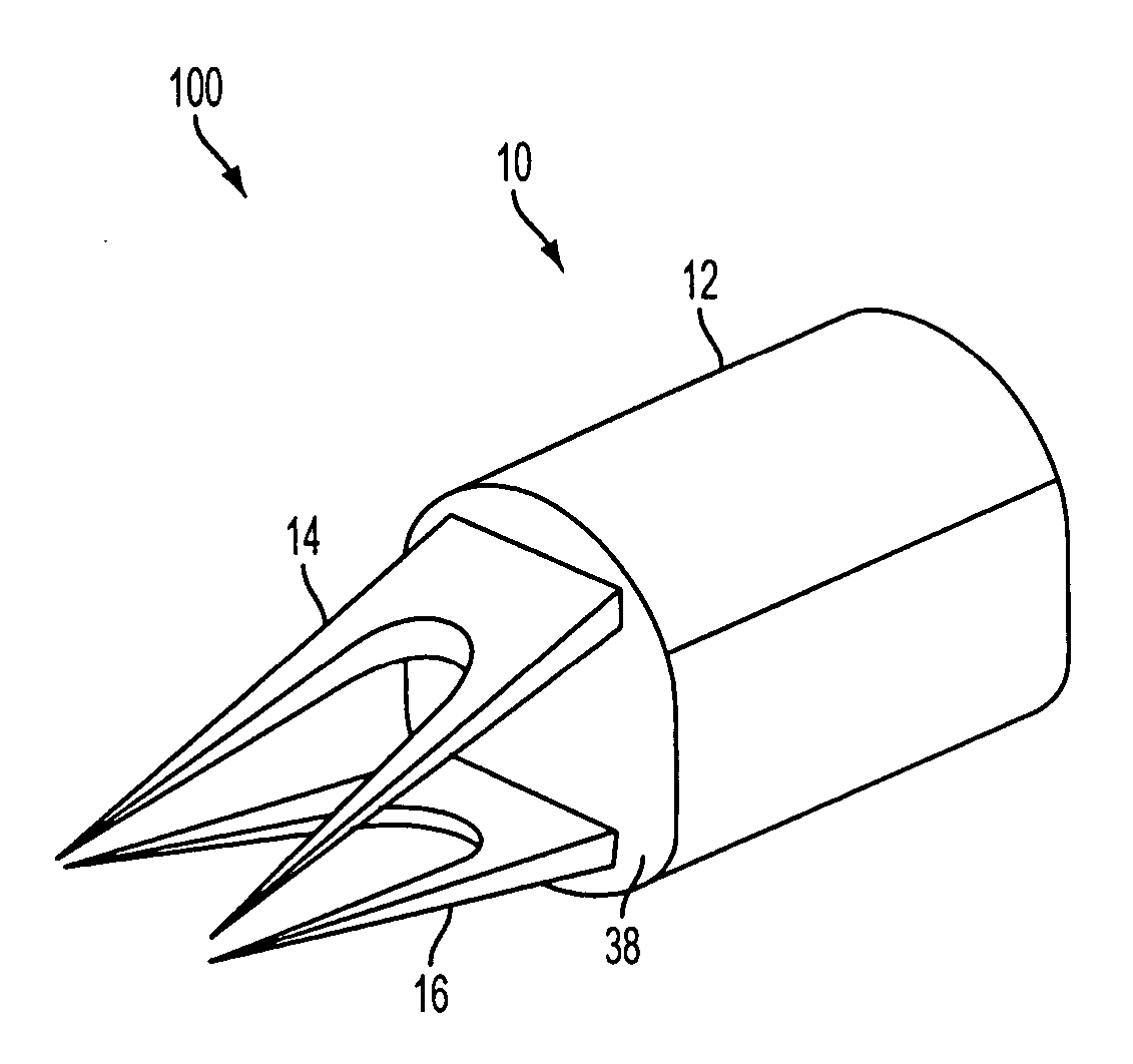
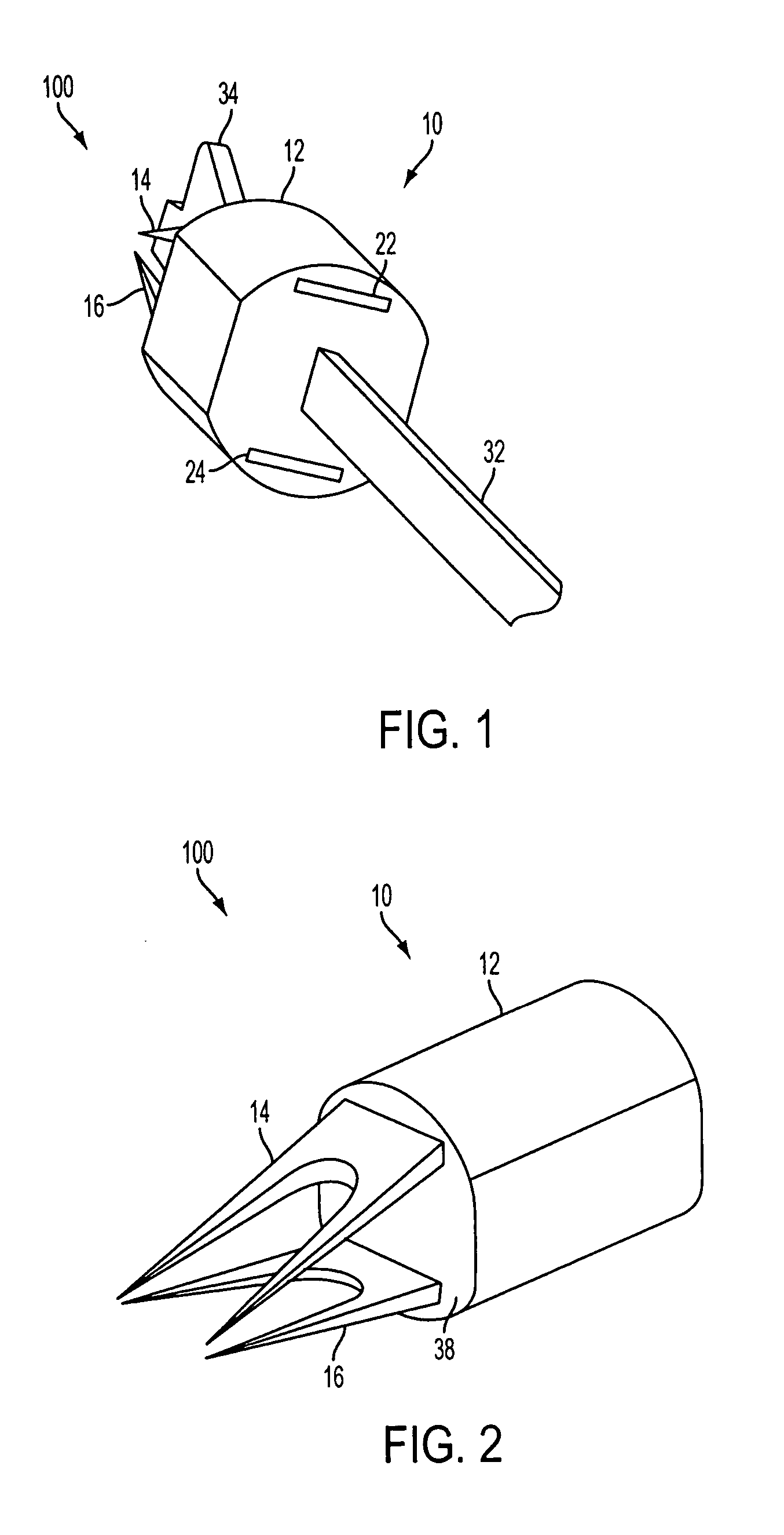
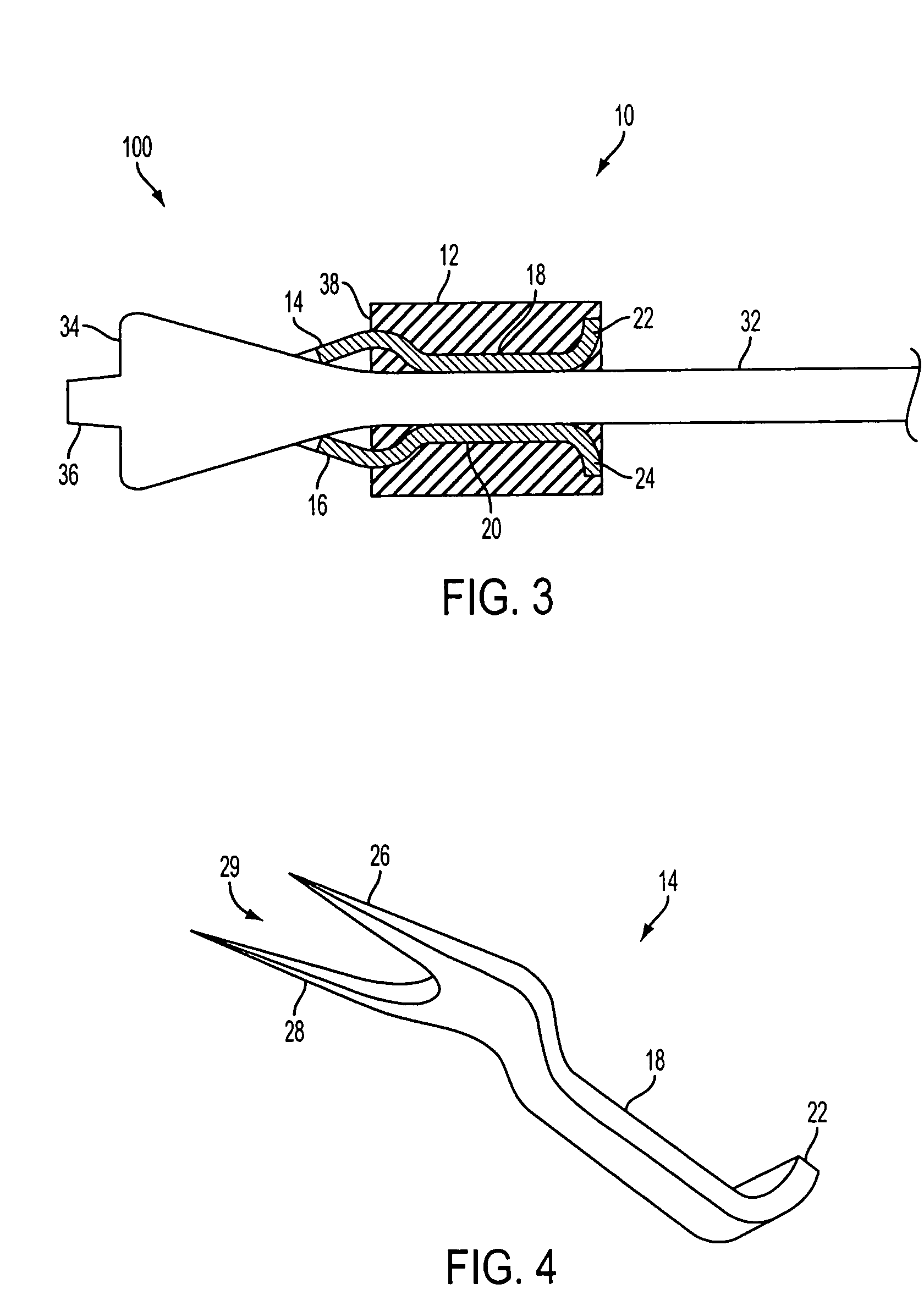
[0021] Referring to FIGS. 1 and 2, a medical stapling system 100 is shown. A staple 10 includes an elastically deformable or resilient body 12 having two or more distinct longitudinal tines 14, 16 enclosed by and extending distally from body 12. Staple 10 may generally be configured for closing a wound, such as a puncture, incision, etc. Staple 10 may be particularly suited for closing a wound formed in a vessel, such as may be created in a blood vessel during the course of a catheterization procedure. Staple 10 may provide wound closure by engaging tines 14...


PUM


Abstract

A self-closing medical staple including a resilient body having an axis and a longitudinal opening, and at least two opposed longitudinal tines spaced about the axis. Each tine is partially enclosed by the body and has a distal end exposed distally of the body. The staple has a closed configuration wherein at least the distal ends of the tines are disposed adjacent to or contacting each other and an open configuration wherein at least the distal ends of the tines are radially separated from each other. A wound closure system includes a mandrel with a flared portion for sliding movement within the longitudinal opening to transform the staple between the open and closed configurations. The system includes a pusher for advancing the staple into tissue surrounding a wound. A method of closing a wound with the self-closing staple is also disclosed.

Description

FIELD OF THE DISCLOSURE [0001] The present disclosure is generally directed to a medical staple, and is more particularly directed to a self-closing medical staple which may be used for closing a vascular wound. A staple, a stapler, and a method in accordance with the invention may be used for blind closure of a puncture arteriotomy. BACKGROUND OF THE DISCLOSURE [0002] Intravascular catheters and catheterization procedures are used for a number of diagnostic and therapeutic applications, and access to the arterial system typically involves insertions into the femoral artery. After a diagnostic or therapeutic catheterization, the arterial wall puncture formed for, or by the catheter must be closed. The size of the puncture opening in the artery corresponds to the size of the catheter or percutaneous introducer sheath used, which devices may typically range in diameter from 5 French (1.67 mm) for a diagnostic procedure to 6-10 French (2.00 mm-3.33 mm) for a therapeutic procedure. Trad...

Claims


Application Information

Patent Timeline
IPC IPC(8): A61B17/08
CPCA61B17/0057A61B17/083A61B2017/00672A61B2017/00668A61B17/1227
Inventor LOBELLO, RICHARD D.
Owner MEDTRONIC VASCULAR INC
Learn More