Split sheath deployment system

a deployment system and split sheath technology, applied in the field of medical devices, can solve the problems of insufficient control of the operator, and insufficient control of the manner of deploymen

Active Publication Date: 2007-10-04
COOK MEDICAL TECH LLC +1
View PDF72 Cites 194 Cited by
  • Summary
  • Abstract
  • Description
  • Claims
  • Application Information

AI Technical Summary

Benefits of technology

[0010] The proximal release mechanism comprises a proximal sheath that is radially disposed over a proximal portion of a prosthesis. The proximal sheath is slidable proximally relative to the prosthesis to release the proximal portion of the prosthesis. The distal release mechanism comprises a distal sheath that is radially disposed over a distal portion of the prosthesis. The distal sheath is slidable distally relative to the prosthesis to release the distal portion of the prosthesis. The proximal release mechanism has a first resistance and the distal release mechanism has a second resistance.
[0011] The relationship between the first and second resistances affects the manner of deployment of the distal sheath and the proximal sheath when the actuation mechanism is deployed in a single coordinated movement. According to an aspect of the invention, the delivery and deployment device may comprise a biasing compensator for regulating the relationship between the first resistance and the second resistance. By regulating the relationship between the first and second resistances, the biasing compensator may control the displacement of the proximal sheath relative to the distal sheath when the actuation mechanism is deployed. At least one or both of the proximal and distal release mechanisms may comprise the biasing compensator. The device may comprise a plurality of biasing elements, where each of the distal and proximal release mechanisms includes at least one of the plurality of biasing elements.
[0012] The biasing compensator may comprise one or more springs, for example, tension springs and / or compression springs. Alternatively, a biasing compensator may comprise other biasing elements, for example a bellows or a compressible gasket. Each of the proximal and distal release mechanisms may comprise the biasing compensator for regulating the displacement of the proximal sheath relative to the distal sheath.

Problems solved by technology

A problem with conventional delivery and deployment systems for radially self-expanding prostheses is that the accuracy and precision of prosthesis placement is dependent on the axial stiffness of the prosthesis.
Axially flexible stents, however, are more sensitive to axial stresses and may be more prone to exhibit axial shortening or elongation during deployment, resulting in potentially inaccurate or imprecise prosthesis placement in the body lumen.
A problem with this system is that it does not provide the operator with sufficient control over the manner of deployment.
For example, if the operator wishes to deploy the prosthesis in a single quick motion, he will be unable to control the rate or the order of deployment of the proximal and distal prosthesis ends.
This is because the manner of deployment can be significantly impacted by internal frictional stresses that can vary from device to device.
The system disclosed in U.S. Pat. No. 5,201,757, however, is generally not capable of providing this level of control to the operator.

Method used


Image

  • Split sheath deployment system
  • Split sheath deployment system
  • Split sheath deployment system

Examples


Embodiment Construction

[0024] Throughout the specification, the terms “distal” and “distally” shall denote a position, direction, or orientation that is, or a portion of a device that, in use, is positioned generally towards the patient. Accordingly, the terms “proximal” and “proximally” shall denote a position, direction, or orientation that is, or a portion of a device that, in use, is positioned generally away from the patient.

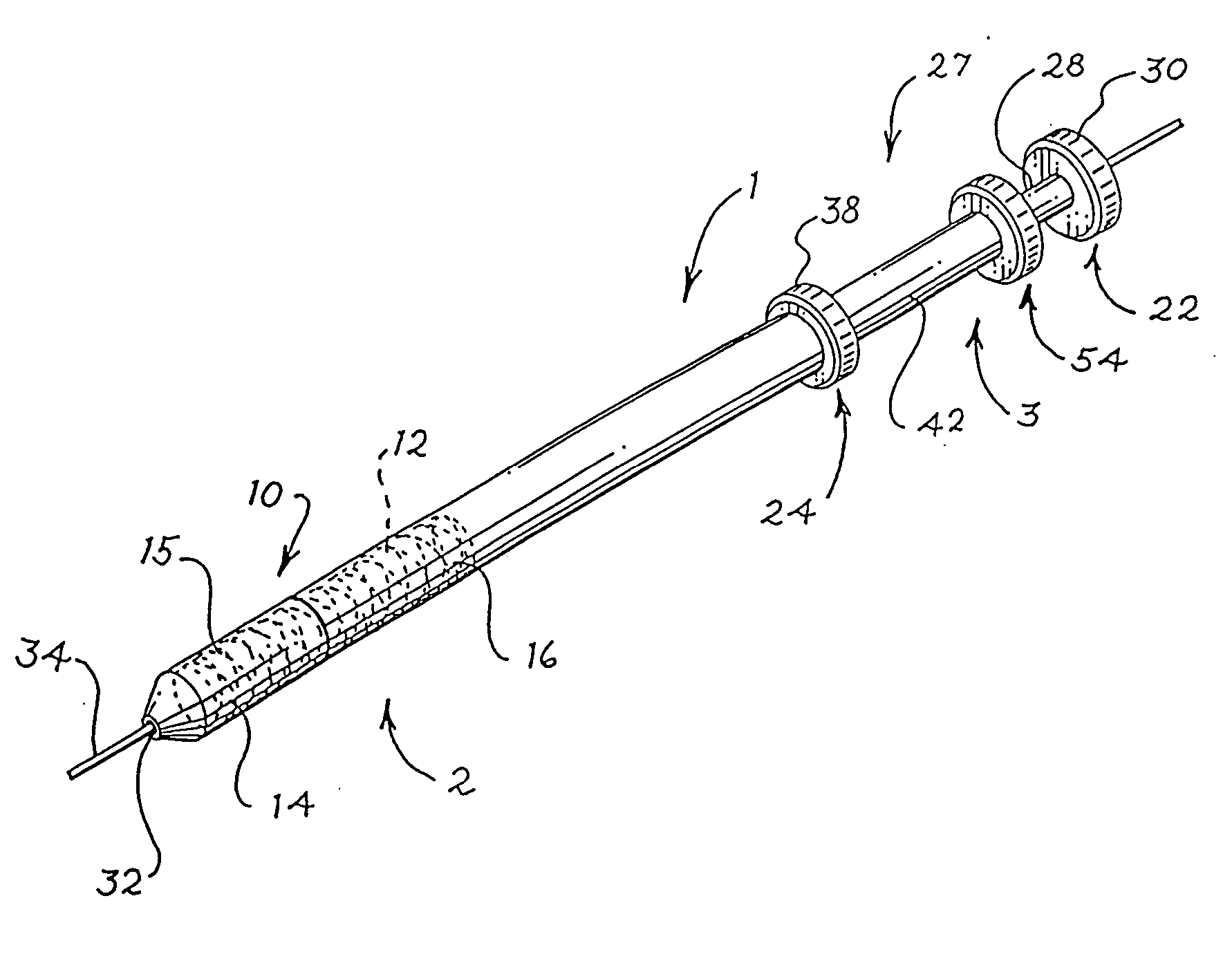
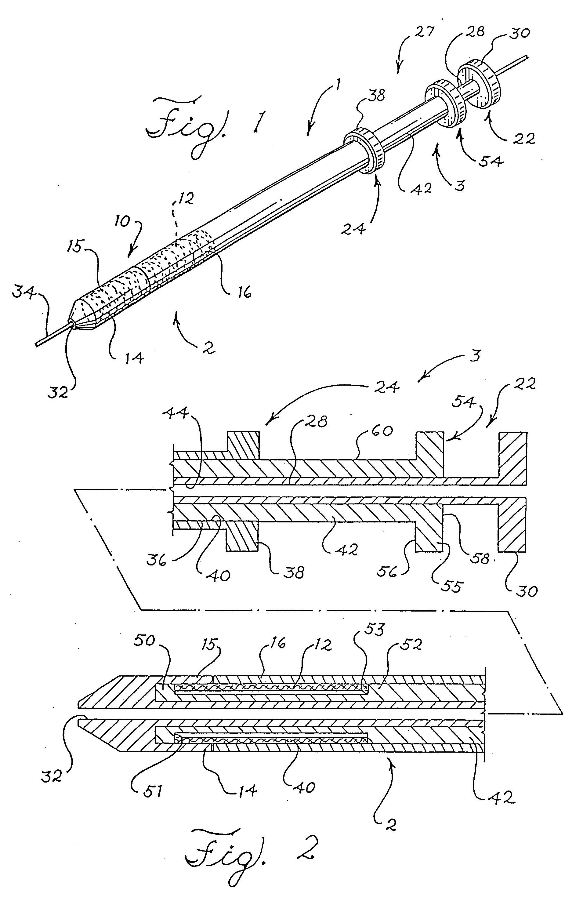
[0025]FIG. 1 shows a prosthesis delivery and deployment device 1. The device 1 is adapted to deliver and deploy an expandable prosthesis into a body lumen (not shown) during a medical procedure and may be adapted for use to repair any damaged or diseased body lumen, including but not limited to the esophagus, the bile duct, or a blood vessel. The device 1 comprises a deployment section 2 and a user interface 3. The deployment section 2 travels through the body lumen during the procedure and delivers the prosthesis to a diseased or damaged portion thereof. The user interface 3 re...


PUM


Abstract

A device for delivering and deploying a radially expandable prosthesis is disclosed and comprises a proximal prosthesis release mechanism having a first resistance and a distal prosthesis release mechanism having a second resistance. The device further comprises an actuation mechanism for actuating the distal and proximal release mechanisms in a single coordinated movement and a biasing compensator for regulating the relationship between the first resistance and the second resistance. Additional aspects of the invention include devices and methods for delivering and deploying a radially expandable prosthesis.

Description

RELATED APPLICATIONS [0001] This application claims the benefit of the filing date under 35 U.S.C. §119(e) of U.S. Provisional Patent Application Ser. No. 60 / 775,187, filed Feb. 21, 2006, which is incorporated herein by reference.BACKGROUND OF THE INVENTION [0002] 1. Field of the Invention [0003] This invention relates to medical devices and, in particular, to delivery and deployment devices for self-expanding prostheses and methods of delivering and deploying a prosthesis into a body lumen. [0004] 2. Description of Related Art [0005] Expandable prostheses, such as stents and stent grafts, are used for treating damaged or diseased body lumens such as the esophagus, bile duct, and blood vessels. The deployment of intraluminal prostheses into the lumen of a patient from a remote location by the use of a delivery and deployment device is well known in the art. Generally, an expandable intraluminal prosthesis is placed on a delivery and deployment device in a radially reduced state and ...

Claims


Application Information

Patent Timeline
Patent Type & Authority Applications(United States)
IPC IPC(8): A61F11/00A61F2/06A61F2/44A61F2/04
CPCA61F2/95A61F2/966A61F2002/9517A61F2002/044A61F2002/041A61F2/9517A61F2/06A61F2/82A61F2/97
Inventor ROEDER, BLAYNE A.LEEWOOD, ALAN R.
Owner COOK MEDICAL TECH LLC
Why Eureka
Try Eureka