
Method of forming a decorative concrete wall

a technology of decorative concrete and tilt-up panels, which is applied in the direction of construction, building components, construction materials, etc., can solve the problems of inability to vibrate concrete, inability to meet the needs of construction, so as to achieve fast construction, reduce cost, and improve the effect of decorative options

Inactive Publication Date: 2007-10-11
MATTHEW TUCKER KENNETH
View PDF59 Cites 10 Cited by
  • Summary
  • Abstract
  • Description
  • Claims
  • Application Information

AI Technical Summary

Benefits of technology

[0013]A general object of the invention is to provide a method for facilitating forming a decorative concrete wall panel for use in tilt-up concrete applications.
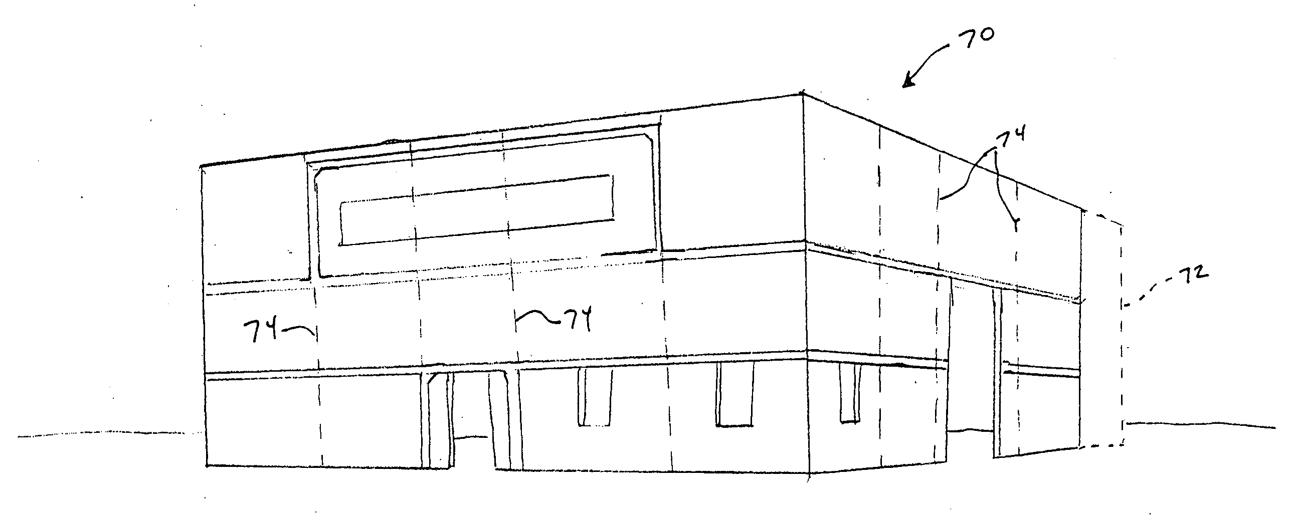
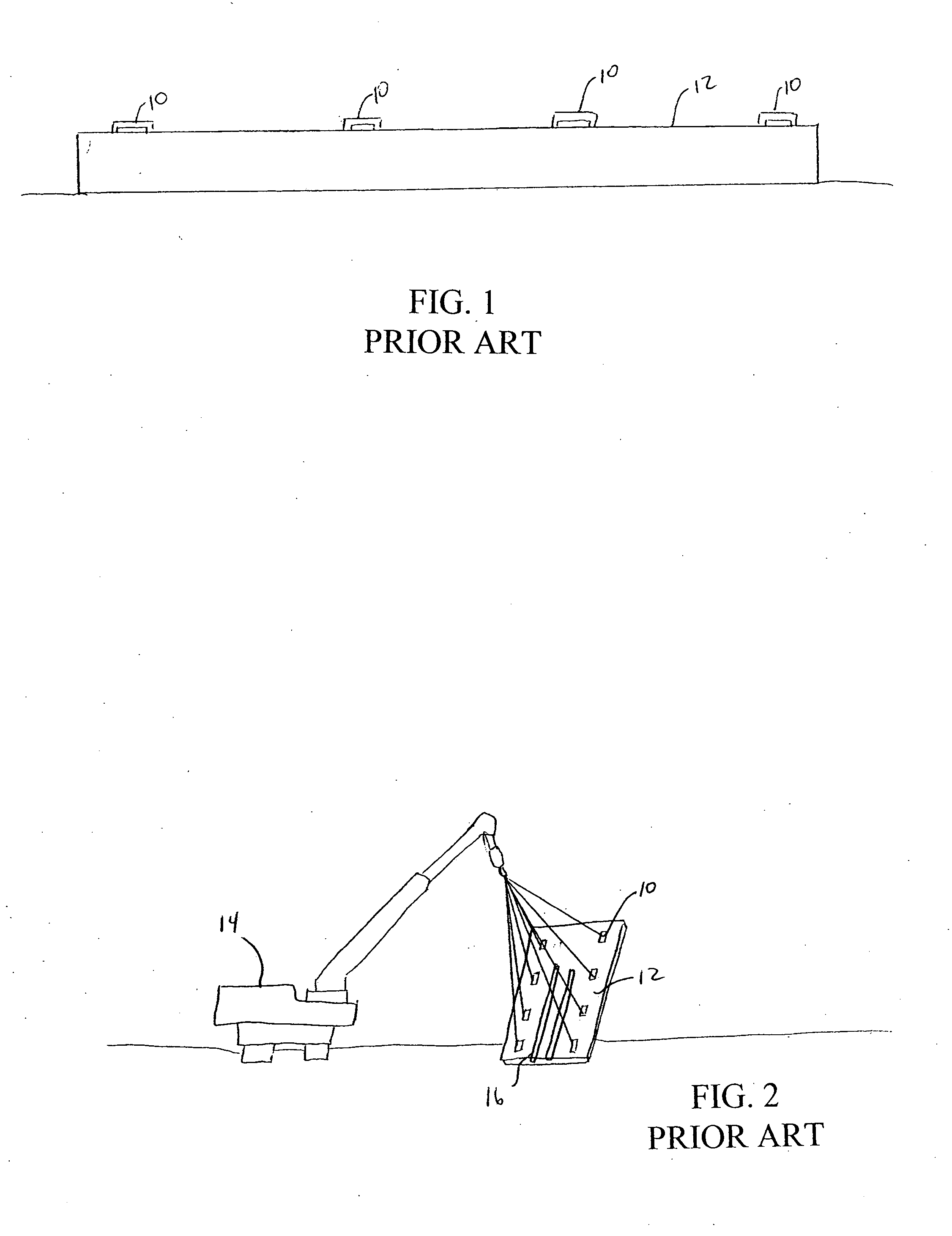
[0017]The method of this invention is an improvement over current processes, such as using a form liner installed prior to pouring a pre-cast or tilt-up concrete wall, which are time consuming, labor intensive processes used to add a brick-stone-slate-rock simulated look to a poured concrete pre-cast or tilt-up wall. The method of this invention allows for relatively faster construction. In one embodiment of this invention, the decorative finish is applied before lifting, and when the wall panel is erected no further work needs to be done to the decorative finish. Other advantages of this invention include: the color does not have to be mixed into the entire wall panel, and can be applied to the surface only before lifting, thereby reducing cost; variations of color and many different colors can be applied to the panel before it is erect, thereby allowing for more decorative options; and the method of this invention is relatively safer as this decorative process is complete on the ground prior to erection of new wall panels.

Problems solved by technology

These current methods make the use of insulation within these concrete panels extremely difficult and costly, if not completely impractical.
Vibrating the concrete also becomes very difficult if not impractical.
There is also no way to “finish” (trowel or smooth) the downward facing concrete surface prior to applying the decorative finish.
Upon erection of the pre-cast or tilt-up wall panels much labor time is spent in complete removal of form liner material as well as touch up work necessary to produce an acceptable finished product.
Coloring must either be done to the entire concrete, thereby increasing cost, or after the panels are lifted into place, thereby requiring additional equipment and increased safety concerns for working high above the ground.

Method used


Image

  • Method of forming a decorative concrete wall
  • Method of forming a decorative concrete wall
  • Method of forming a decorative concrete wall

Examples


Embodiment Construction

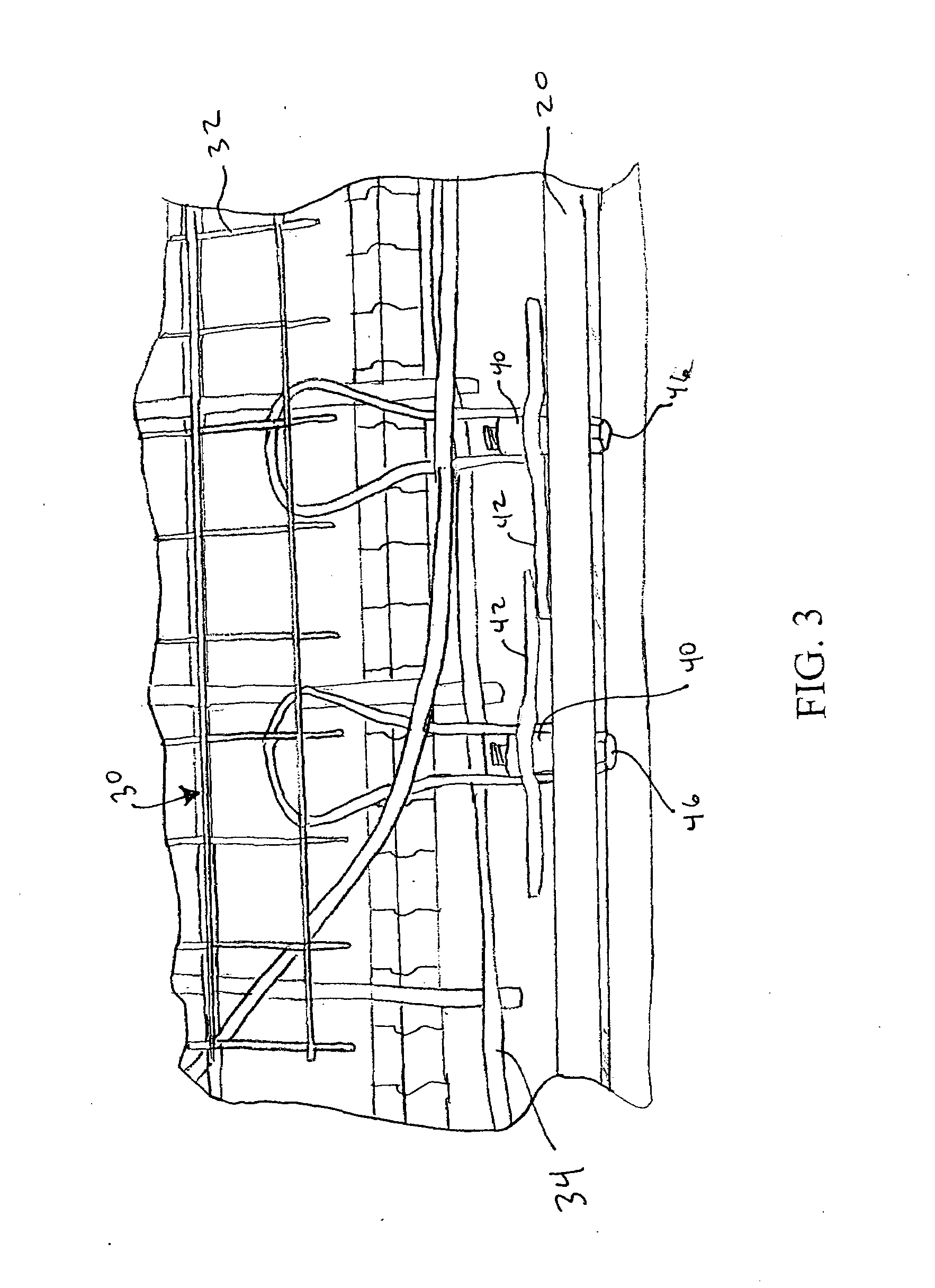
[0025]According to one embodiment of this invention, a decorative concrete wall is produced at a construction site where the wall will be used. To create the wall panel on site, a mold form is created and laid on a flat surface, such as, for example, an already formed concrete floor structure. The mold form is desirably made from wood boards, or steel, and is made according to the size and shape of the desired concrete wall panel. The mold form is the outside perimeter of the wall panel, and also desirably includes internal forms for any doors and / or windows that are to be formed within the perimeter of the wall panel.

[0026]FIG. 3 illustrates a partial view of a mold form 20. Once the mold form 20 is created, a support structure 30 is placed into the mold form 20. The support structure 30 can include any suitable concrete support known and available to those skilled in the art. For example, a combination of steel grid 32 and rebar 34 can be used to form the support structure 30, as ...


PUM


Abstract

A method of constructing a concrete wall. A mold form is placed upon on a surface at a construction site. A support structure is placed into the mold form and concrete is poured around the support structure within the mold form to form a concrete panel. The upward facing surface of the poured panel is altered with one or more of a color, a texture, and a pattern to form a decorative concrete panel while the panel lies on the ground. The decorative concrete panel is then lifted into an upright position by a crane connected to lifting inserts of the panel. The lifting inserts are desirably located at a side or top end of the panel and not in the decorative surface.

Description

CROSS REFERENCE TO RELATED APPLICATION[0001]This application claims the benefit of Provisional U.S. Application, Ser. No. 60 / 785,152, filed on 23 Mar. 2006. The co-pending provisional application is hereby incorporated by reference herein in its entirety and is made a part hereof, including but not limited to those portions which specifically appear hereinafter.BACKGROUND OF THE INVENTION[0002]1. Field of the Invention[0003]This invention is directed to preformed tilt-up concrete panels, i.e., preformed panels that are then lifted and set into place, such as by a crane.[0004]2. Discussion of Related Art[0005]Tilt-up concrete construction has been around for many years. It has developed into a preferred method of construction for many types of buildings and structures. Nationwide, over 15% of all industrial buildings are constructed using tilt-up construction, typically ranging in size from 5,000 to over 1.5 million square feet. Such buildings are typified by their attractiveness, ef...

Claims


Application Information

Patent Timeline
IPC IPC(8): E04C1/00
CPCE04C2/06
Inventor MATTHEW TUCKER, KENNETH
Owner MATTHEW TUCKER KENNETH
Learn More