Heating and cooling device

a cooling device and cooling element technology, applied in the direction of light and heating apparatus, machine operation mode, transportation and packaging, etc., can solve the problems of increase of the cost of manufacturing the heating and cooling device, and overheating etc., to achieve the effect of reducing the abnormal temperature increase of the peltier elemen

Inactive Publication Date: 2007-10-11
DENSO CORP
View PDF5 Cites 95 Cited by
  • Summary
  • Abstract
  • Description
  • Claims
  • Application Information

AI Technical Summary

Benefits of technology

[0012]Accordingly, an abnormal temperature increasing of the Peltier element can be reduced.

Problems solved by technology

However, when the fan is stopped for any reason even though the fan and the Peltier element are in the operating condition, air is not sent to the Peltier element, for example.
At this time, the Peltier element may be overheated, because air is not sent to the Peltier element.
Therefore, a temperature of the Peltier element may be abnormally increased.
Thus, cost for manufacturing the heating and cooling device may be increased.

Method used


Image

  • Heating and cooling device
  • Heating and cooling device
  • Heating and cooling device

Examples


first embodiment

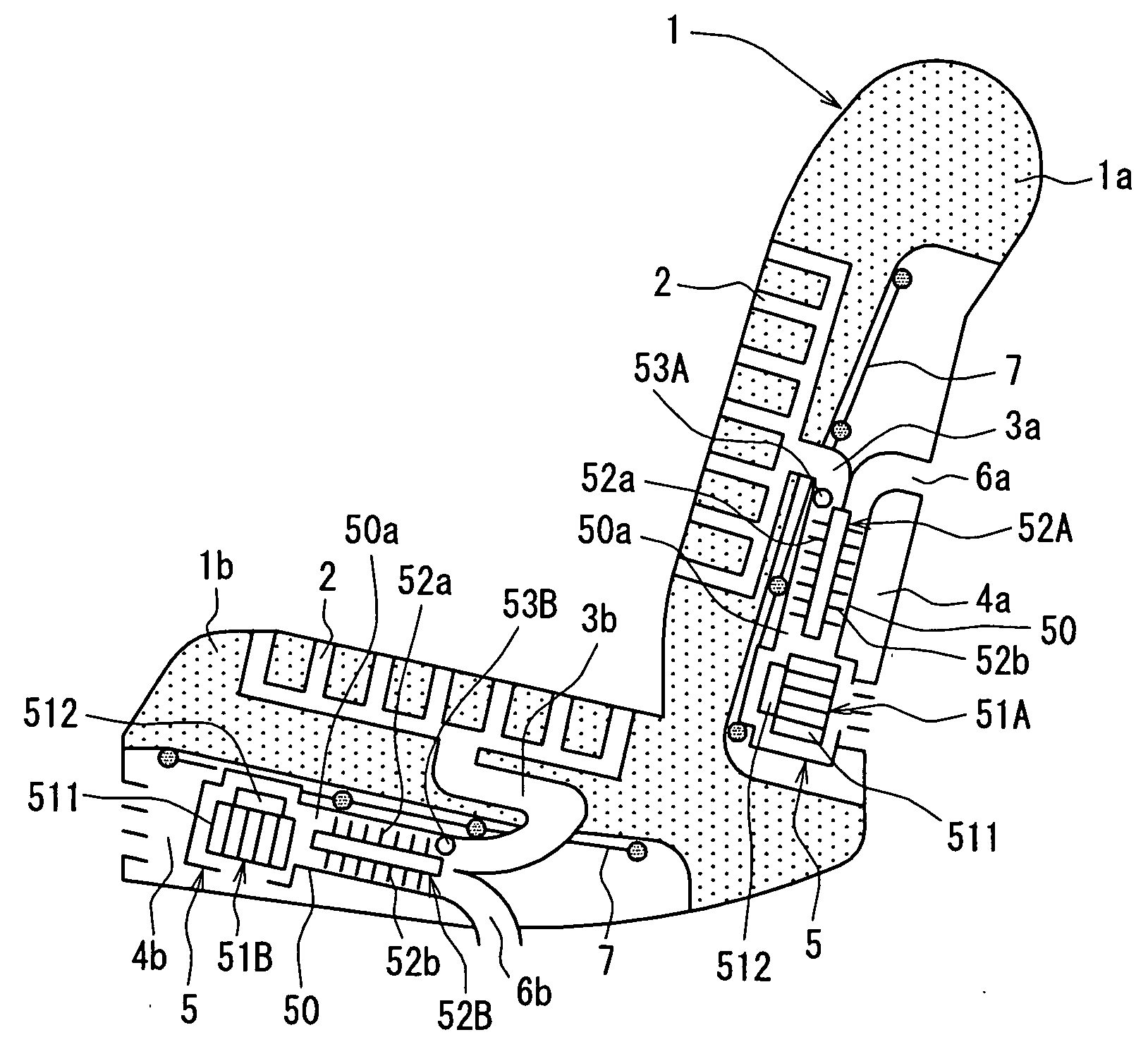
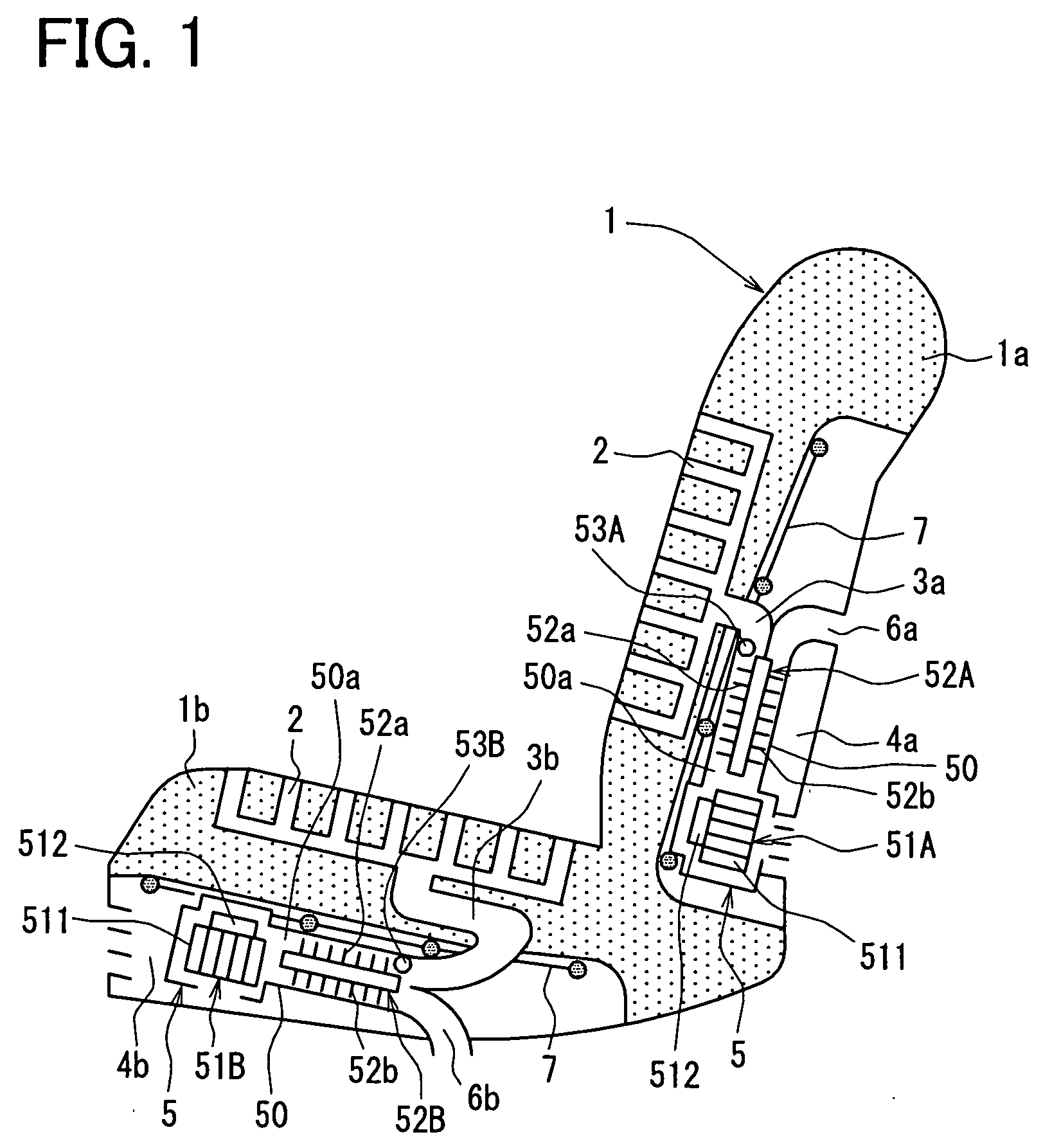
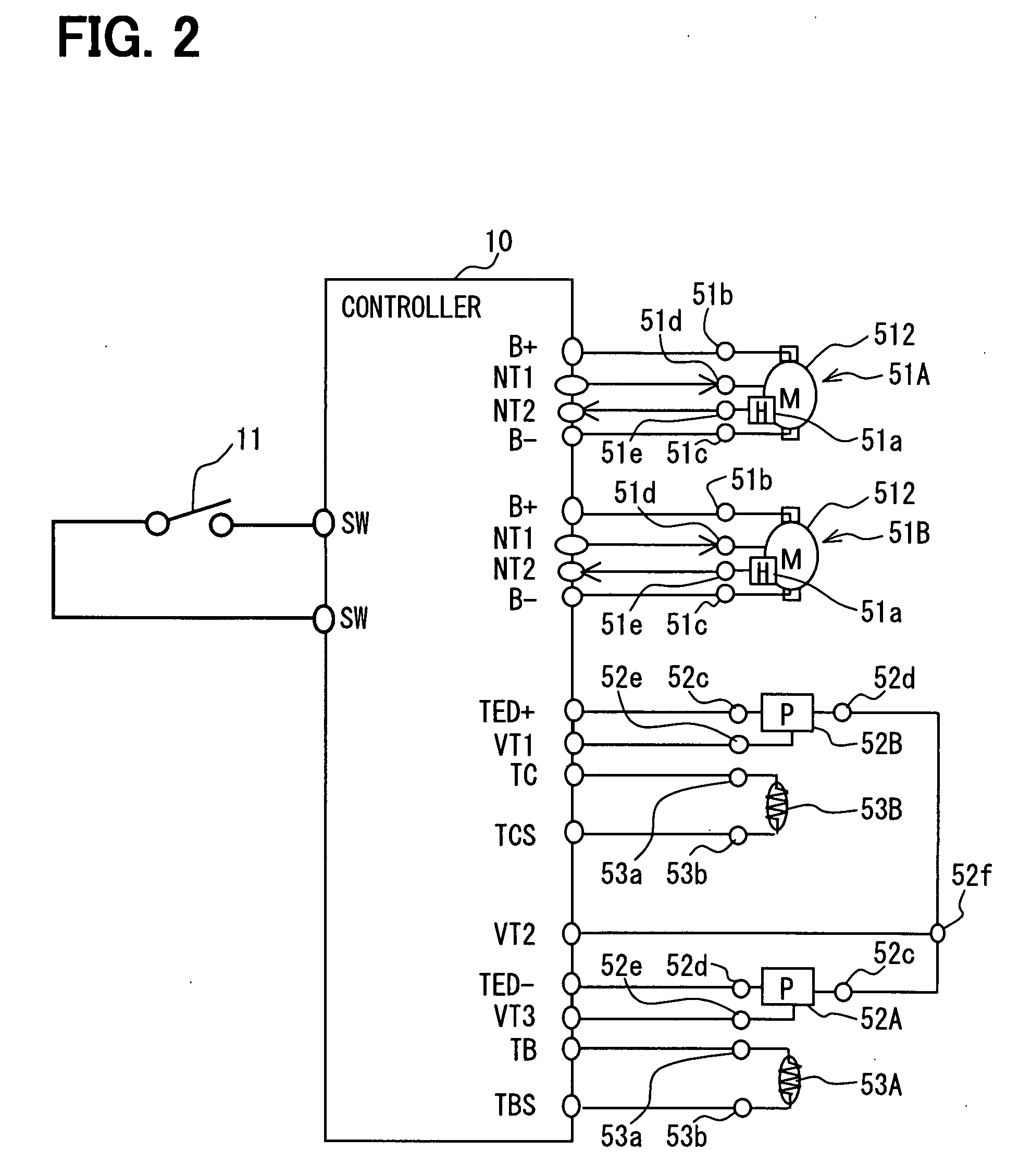
[0022]A first embodiment will be described with reference to FIGS. 1-3. As shown in FIG. 1, a seat 1 includes a seat back 1a and a seat bottom 1b, and a heating and cooling device 5 is used in each of the seat back 1a and the seat bottom 1b. A first space 4a is provided in the seat back 1a, and a second space 4b is provided in the seat bottom 1b. A controller 10 shown in FIG. 2 controls the heating and cooling device 5.

[0023]A first duct 3a communicating with the first space 4a is provided in the seat back 1a, and plural air-blowing holes 2 communicating with the first duct 3a are provided in the seat back 1a. A second duct 3b communicating with the second space 4b is provided in the seat bottom 1b, and plural air-blowing holes 2 communicating with the second duct 3b are provided in the seat bottom 1b.

[0024]The heating and cooling device 5 is arranged in each of the first space 4a and the second space 4b. Specifically, the heating and cooling device 5 is supported by a net-shaped s...

second embodiment

[0060]A second embodiment will be described with reference to FIGS. 4-6. As shown in FIG. 4, a duct 54 is disposed between the blower 51A, 51B and the Peltier element 52A, 52B in the second embodiment.

[0061]Specifically, the duct 54 has a wave shape. An end of the duct 54 is connected to a discharge side of the blower 51A, 51B, and the other end of the duct 54 is connected to the case 50 of the Peltier element 52A, 52B. Thereby, the heating and cooling device 5 can be easily mounted in the space 4a, 4b of the seat 1 having a complicated shape.

[0062]When electricity is supplied to the Peltier element 52A, 52B, the duct 54 may be disconnected (detached) by vibration of the vehicle. The disconnection of the duct 54 can be detected in the second embodiment.

[0063]Specifically, as shown in FIG. 5, step 165 is provided between step 160 and step 170. At step 165, the number N of revolutions of the detected revolution signal input at step 160 is compared with a predetermined number R2 of rev...

third embodiment

[0069]A third embodiment will be described with reference to FIGS. 7 and 8. In the above embodiments, the hall element 51a detects the driving state of the blower 51A, 51B, when a brushless motor is used as the motor 512. However, when a motor having brush is used as the motor 512, current flowing through the blower 51A, 51B can be detected.

[0070]Specifically, as shown in FIG. 7, the controller 10 has the positive electrode side power terminal B+, the negative electrode side power terminal B− and a driving current input terminal Ip, in order to be connected to the motor 512 of the blower 51A, 51B. Further, the motor 512 of the blower 51A, 51B has the power input terminal 51b, the power output terminal 51c and a driving current detection terminal 51f.

[0071]The power input terminal 51b is connected to the positive electrode side power terminal B+. The power output terminal 51c is connected to the negative electrode side power terminal B−. The driving current detection terminal 51f is...


PUM


Abstract

A heating and cooling device includes a case having an air passage, a blower for sending air to the air passage, a thermoelectric conversion element and a controller. The thermoelectric conversion element is disposed in the case, and has a heat-absorbing part and a heat-emitting part, which are switched based on a current direction. The thermoelectric conversion element heats or cools air sent by the blower by switching the current direction. The controller stops electricity supplied to the thermoelectric conversion element, when air sent by the blower toward the thermoelectric conversion element is stopped while the thermoelectric conversion element is supplied with electricity.

Description

CROSS REFERENCE TO RELATED APPLICATION[0001]This application is based on Japanese Patent Applications No. 2006-106785 filed on Apr. 7, 2006, and No. 2006-355966 filed on Dec. 28, 2006, the disclosure of which are incorporated herein by reference.BACKGROUND OF THE INVENTION[0002]1. Field of the Invention[0003]The present invention relates to a heating and cooling device having a thermoelectric conversion element.[0004]2. Description of Related Art[0005]JP-A-2006-21572 discloses a heating and cooling device. The heating and cooling device includes a Peltier element (thermoelectric conversion element) and a fan, and is disposed in a seat of a vehicle. A hole for blowing air and a duct communicating with the hole are provided in the seat. The Peltier element converts electricity into heat, and the fan sends air toward the hole.[0006]When air is cooled at a low-temperature side of the Peltier element and the cooled air is blown through the hole, heat generated at a high-temperature side ...

Claims


Application Information

Patent Timeline
Patent Type & Authority Applications(United States)
IPC IPC(8): F25B21/02
CPCB60H1/00285B60H1/00478B60H2001/003B60N2/5635F25B2700/2107B60N2/5685B60N2/5692F25B21/04B60N2/5657
Inventor AOKI, SHINJIITO, YUJI
Owner DENSO CORP
Why Eureka
Try Eureka