Tightness Test for Mems or for Small Encapsulated Components

a technology of encapsulation and tightness, which is applied in the direction of microstructural devices, microstructural technology, material thermal analysis, etc., can solve the problems of complex method, cumbersome tightness of mems or small devices, and difficult reproducibility

Inactive Publication Date: 2007-10-11
COMMISSARIAT A LENERGIE ATOMIQUE ET AUX ENERGIES ALTERNATIVES
View PDF7 Cites 11 Cited by
  • Summary
  • Abstract
  • Description
  • Claims
  • Application Information

AI Technical Summary

Problems solved by technology

If fluid A is detected, this means that there is a tightness defect.
This direct testing of the tightness of the cavity of MEMs or small devices is a cumbersome, complex method that cannot be performed collectively, and is often difficult to reproduce throughout the lifetime of the MEMS or small device to verify the proper functioning thereof.
It requires a highly sensitive fluid detector, this type of apparatus often being complex and / or costly.
If it is performed collectively on a certain number of MEMS or small devices e.g. on a fabrication wafer before cutting out the MEMS, a leak on only one of the devices leads to the discarding of the entirety of the tested devices.
The difference in pressure either side of the membrane exerts stresses on this membrane which cause deformations and movements of the membrane.
The incorporation of a pressure sensor within the cavity of the MEMS or small device is a costly, complex method of proceeding which often requires extensive modification of fabrication processes initially designed or optimized for the main function of the MEMS or small device, and in some cases may entail unacceptable space requirements.
In addition, there are cases when it is impossible to incorporate a pressure sensor whilst maintaining the main function of the MEMS or small device.

Method used


Image

  • Tightness Test for Mems or for Small Encapsulated Components
  • Tightness Test for Mems or for Small Encapsulated Components
  • Tightness Test for Mems or for Small Encapsulated Components

Examples


Embodiment Construction

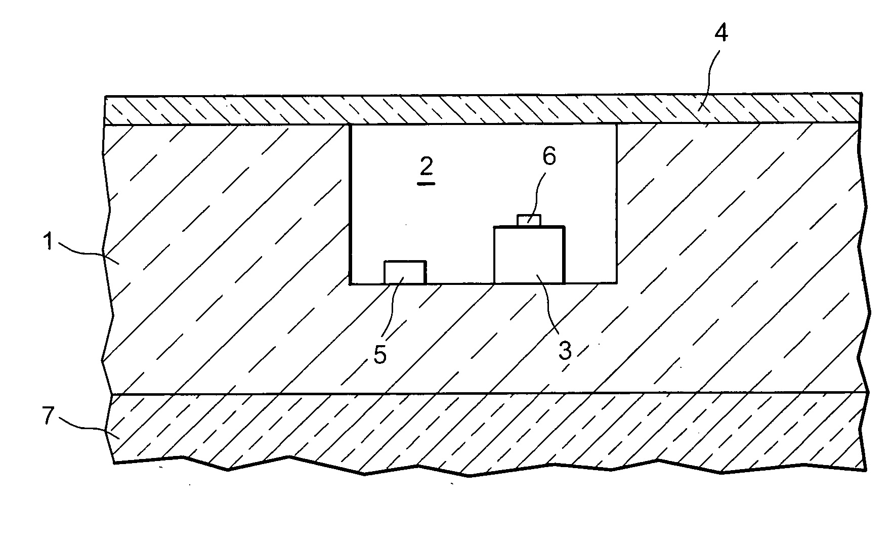
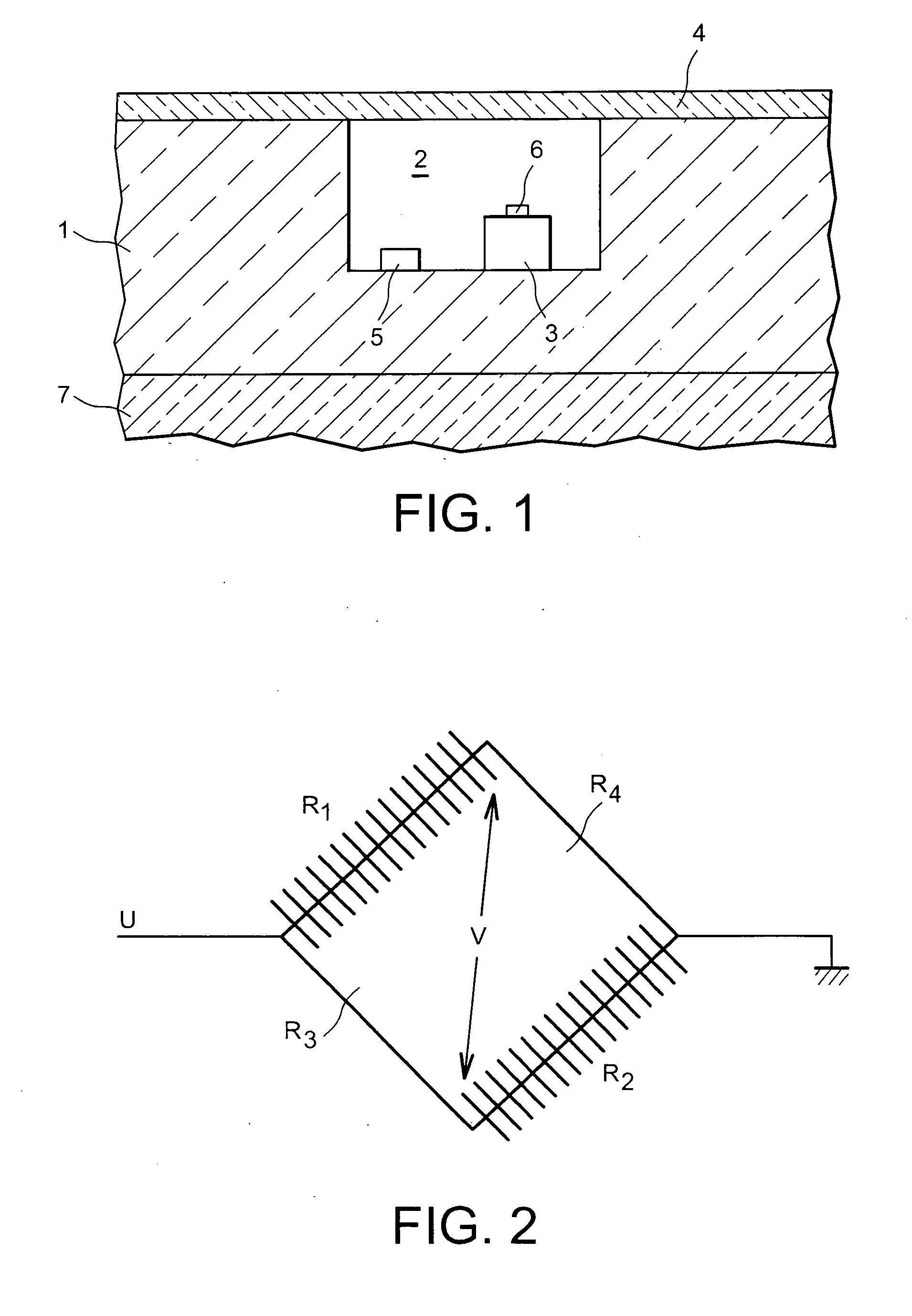
[0014] To overcome the disadvantages of the prior art, the present invention proposes the incorporation of a simplified detector within the cavity to detect gas density, inspired from Pirani-type pressure sensors and using the same techniques and / or methods as those designed and optimized for the main function of the MEMS or small device. For this purpose, use is made of the fact that when the mean free path of molecules is no longer very small compared with the dimensional characteristic of gas thickness, a temperature jump occurs in the vicinity of a heat-exchanging wall as modelled over one century ago by von Smoluchowski (1898) as: Tgas-Twall=2-σTσT·2⁢ ⁢γγ+1·LPr·∇->⁢Tgas*n->

wherein

[0015]σT: coefficient of thermal accommodation, between 0 and 1, dependent on the surface properties and type of gas. It is often taken to be in the order of 0.75 to 1.

[0016]γ=Cp / Cv: isentropic coefficient of the gas, typically in the order of 1.4 for a diatomic gas.

[0017] Pr: number of Pran...


PUM

PropertyMeasurementUnit
pressuresaaaaaaaaaa
pressuresaaaaaaaaaa
pressuresaaaaaaaaaa

Abstract

A tightness testing method for a MEMS or small encapsulated component, the MEMS or small component being housed in a cavity of a carrier. The cavity being sealed and containing a gas having a different density to the density it would have if subjected to the pressure of the medium outside the cavity. The method measures the density of the gas contained in the cavity.

Description

TECHNICAL AREA [0001] The invention concerns the testing of the tightness seal of MEMS or small encapsulated components. [0002] The object is to verify the tightness of small devices containing inner cavities which are normally under a pressure different to air pressure or to the pressure of the environment in which the MEMS or small device are intended to operate. It therefore also applies to verifying the tightness of encapsulated MEMS. It is often necessary, in order to guarantee reliable, lasting, proper functioning of the MEMS or small device, to be able to guarantee the seal of the cavity. [0003] One particular case for this need is when proper functioning requires the quantity of gas (this quantity possibly being zero if the cavity is to be maintained in a vacuum) to remain constant in the cavity. By way of example, numerous types of pressure sensors, accelerometers and gyrometers have this constraint. [0004] Another particular case for this need is when the proper functionin...

Claims


Application Information

Patent Timeline
Patent Type & Authority Applications(United States)
IPC IPC(8): G01N25/18B81C99/00G01L21/12G01M3/00
CPCG01M3/3281G01M3/002
Inventor DE CRECY, FRANCOISDIEM, BERNARD
Owner COMMISSARIAT A LENERGIE ATOMIQUE ET AUX ENERGIES ALTERNATIVES
Why Eureka
Try Eureka