Electronic throttle control with hysteresis and kickdown

a technology of electronic throttle control and electronic control, which is applied in the direction of mechanical control devices, process and machine control, instruments, etc., can solve the problems of increased foot fatigue of drivers from the rapid adjustment of the pedal, complicated hysteresis devices, and high cost, and achieves simple design, enhanced packageability within the interior environment, and integrated hysteresis and kickdown generating devices.

Inactive Publication Date: 2007-10-11
KSR IP HLDG
View PDF21 Cites 19 Cited by
  • Summary
  • Abstract
  • Description
  • Claims
  • Application Information

AI Technical Summary

Benefits of technology

[0010]One advantage of the present invention is that an electronically controlled pedal assembly is provided that includes an integrated hysteresis and kickdown device to simulate both the resistance to depression of the pedal and downshift of the transmission during acceleration. Another advantage of the present invention is that the integrated hysteresis and kickdown generating device for the electronically controlled pedal is simpler in design than previous atte

Problems solved by technology

However, since the pedal arm is not attached to a mechanical device, such as a rod or cable, there is no resistance to depression of the pedal, and the pedal returns to a nominal position quicker than with a mechanical system.
Without a predetermined amount of hysteresis in the pedal, the driver may experience increased foot fatigue from

Method used


Image

  • Electronic throttle control with hysteresis and kickdown
  • Electronic throttle control with hysteresis and kickdown
  • Electronic throttle control with hysteresis and kickdown

Examples


Embodiment Construction

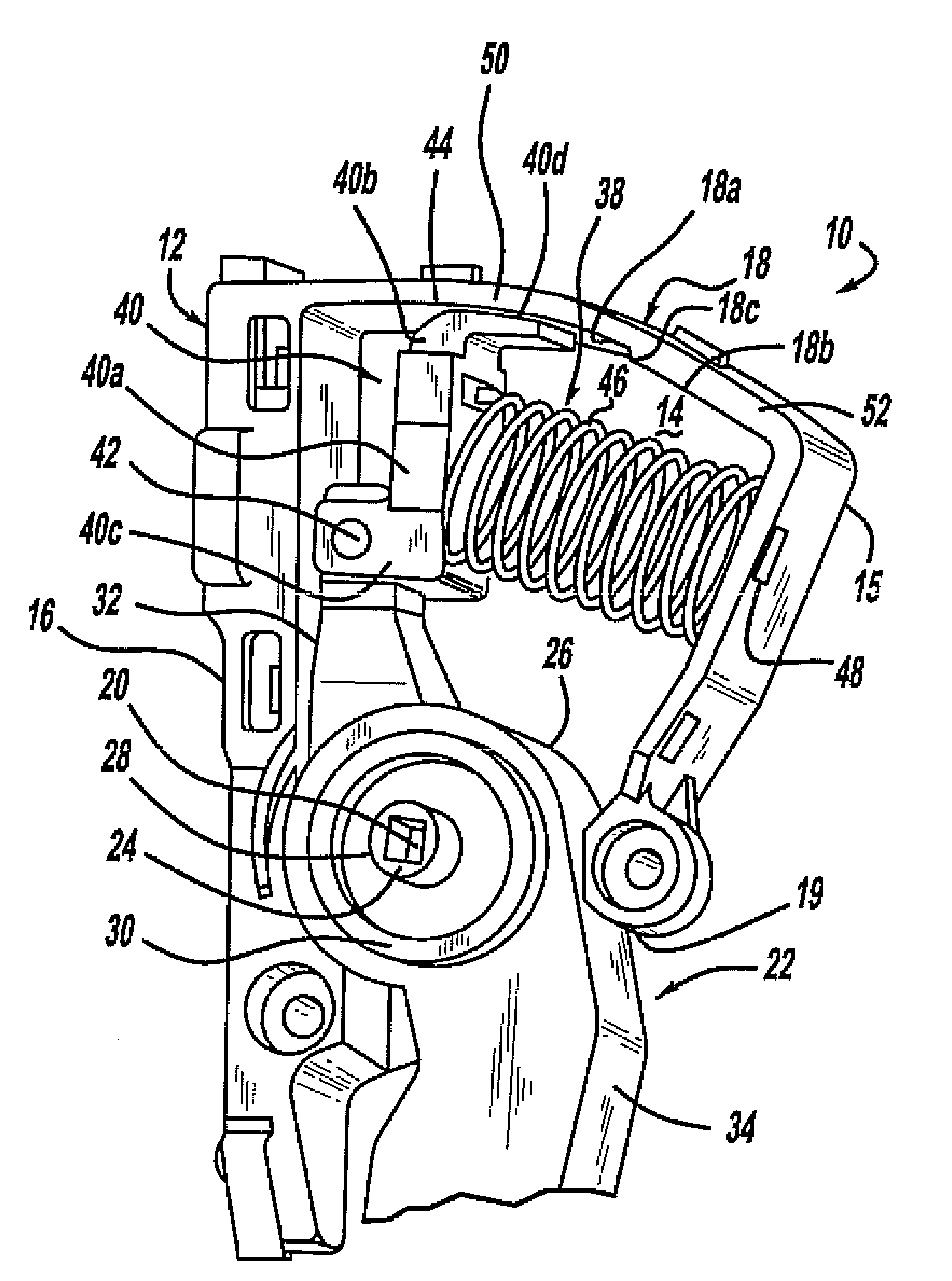
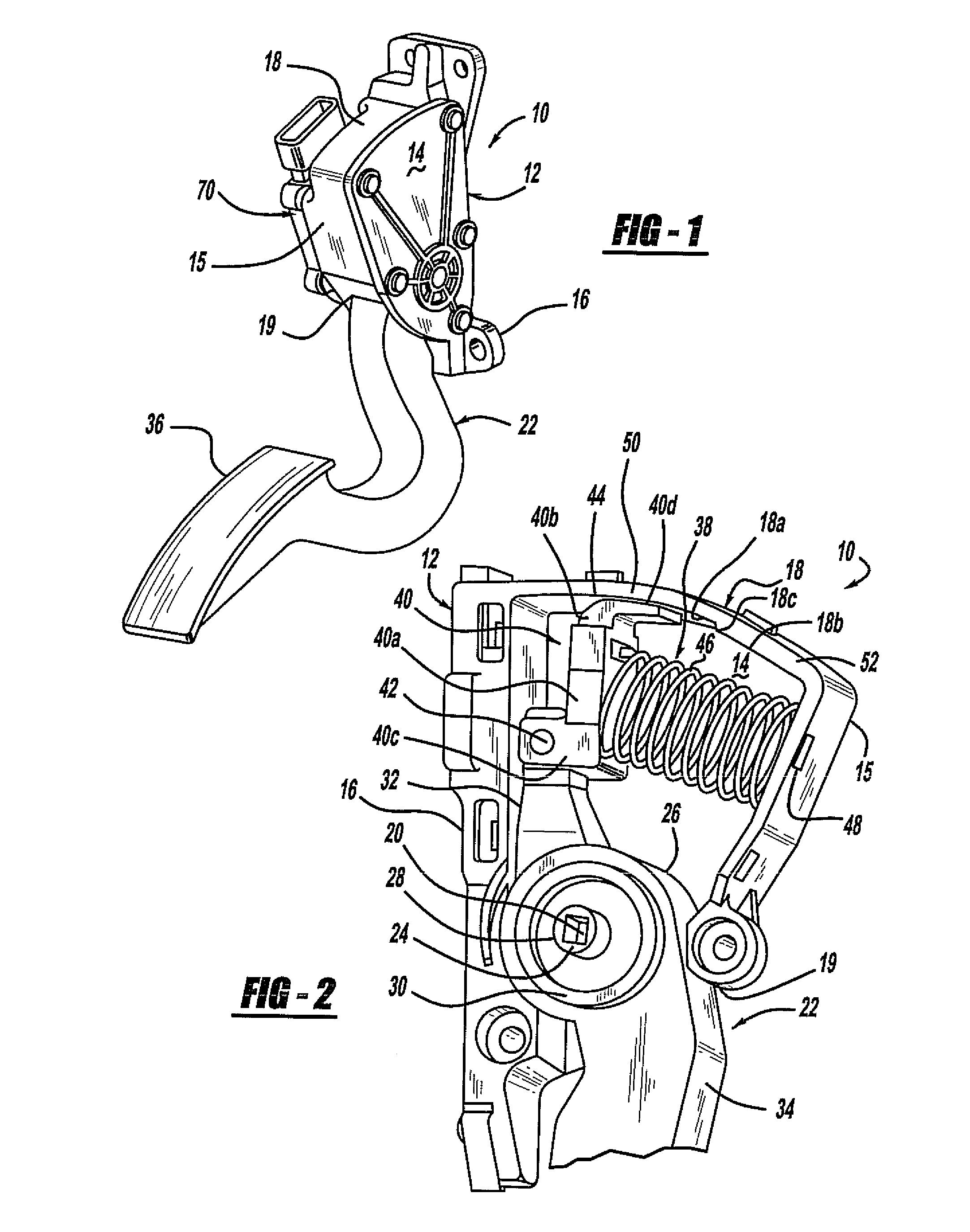
[0021]Referring to FIGS. 1 and 2, an electronically controlled pedal assembly is illustrated. It should be appreciated that in this example the electronically controlled pedal is a throttle pedal for a vehicle, such as an automotive vehicle. In addition, the vehicle includes an electronically controlled automatic transmission.

[0022]The electronic throttle control pedal assembly 10 of this example transmits a signal from the driver to a throttle controller (not shown) regarding movement of the vehicle. The pedal assembly 10 includes a housing 12 having a mounting wall with tabs 16 for mounting the pedal assembly 10 to a vehicle (not shown). The housing includes a pair of spaced apart side walls 14 and a curved end wall 15 between the side walls 14 that define a cavity. An opening is formed in the lower portion of the housing as shown at 19, between the end wall 15 and the mounting wall 16.

[0023]The end wall 15 includes a friction wall portion 18 that has an overall arcuate shape and ...


PUM


Abstract

An electronically controlled pedal with hysteresis and kickdown includes a housing having a friction wall with a first frictional surface having a first radius of curvature, a second frictional surface having a second radius of curvature, and a step transitioning between the two. A hysteresis and kickdown generating means is pivotally attached to the upper pedal arm. A spring biases the generating means against the housing. Application of a first pedal load to the pedal arm generates a first hysteresis force between the hysteresis and kickdown generating means and the first frictional surface. Application of a second pedal load to the pedal arm generates a frictional kickdown force between the generating means and the step, and application of a third pedal load generates a second hysteresis force between the generating means and the second frictional surface. The first hysteresis force, kickdown force and second hysteresis force are transmitted back to the operator.

Description

CROSS-REFERENCE TO RELATED APPLICATIONS[0001]This application claims priority of U.S. Provisional Patent Application Ser. No. 60 / 790,269 filed Apr. 7, 2006, which is incorporated herein by reference.BACKGROUND OF THE INVENTION[0002]1. Field of the Invention[0003]The present invention relates generally to electronic controls for vehicles, and more particularly, to an electronically controlled pedal with hysteresis and kickdown.[0004]2. Description of the Related Art[0005]Vehicles, and in particular automotive vehicles, utilize a foot-operated device, such as a brake pedal or a throttle control pedal, also referred to as an accelerator pedal, to control the movement of the vehicle. Conventional brake systems include a brake pedal for transmitting a braking force from the vehicle operator to the wheels of the vehicle. Similarly, conventional throttle control systems include a throttle pedal to transmit a signal from the vehicle operator to a controller to control acceleration and movem...

Claims


Application Information

Patent Timeline
IPC IPC(8): G05G1/14G05G1/38
CPCF16H59/20Y10T74/20534G05G5/03G05G1/38B60K26/02B60T7/04F02D9/08F02D11/02
Inventor ELLIOTT, RYAN W.
Owner KSR IP HLDG
Why Eureka
Try Eureka