Laser imaging apparatus with variable patient positioning

a patient positioning and laser imaging technology, applied in the field of diagnostic optical imaging apparatus, can solve the problems of breast cancer, insufficient x-ray absorption density resolution of present photographic x-ray methods to provide reliable early detection of malignant tumors, and rare mammogram contrast of tumors of this size to achieve detection. , to achieve the effect of widening the breast shape rang

Active Publication Date: 2007-10-11
IMAGING DIAGNOSTIC SYST
View PDF23 Cites 30 Cited by
  • Summary
  • Abstract
  • Description
  • Claims
  • Application Information

AI Technical Summary

Benefits of technology

[0010] It is an object of the present invention to provide a laser imaging apparatus that acquires photon intensity data by direct observation of the surface of a scanned object, particularly of a breast, reconstructs cross-sectional images of the optical properties of the breast, and accommodates a relatively wider range of breast shapes and therefore patients.

Problems solved by technology

Cancer of the breast is a major cause of death among the American female population.
The x-ray absorption density resolution of present photographic x-ray methods is insufficient to provide reliable early detection of malignant tumors.
Tumors of this size rarely produce sufficient contrast in a mammogram to be detectable.
For these reasons, photographic mammography has been relatively ineffective in the detection of this condition.
Most mammographic apparatus in use today in clinics and hospitals require breast compression techniques that are uncomfortable at best and in many cases painful to the patient.
In addition, x-rays constitute ionizing radiation, which adds a further risk factor into the use of mammographic techniques as most universally employed.

Method used


Image

  • Laser imaging apparatus with variable patient positioning
  • Laser imaging apparatus with variable patient positioning
  • Laser imaging apparatus with variable patient positioning

Examples


Embodiment Construction

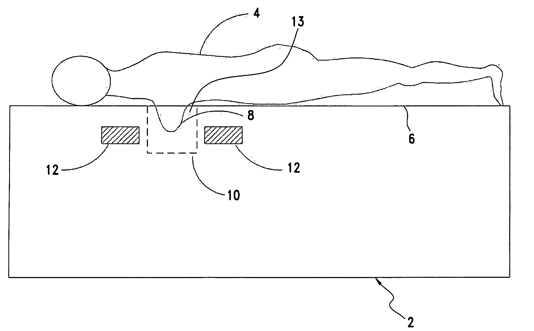
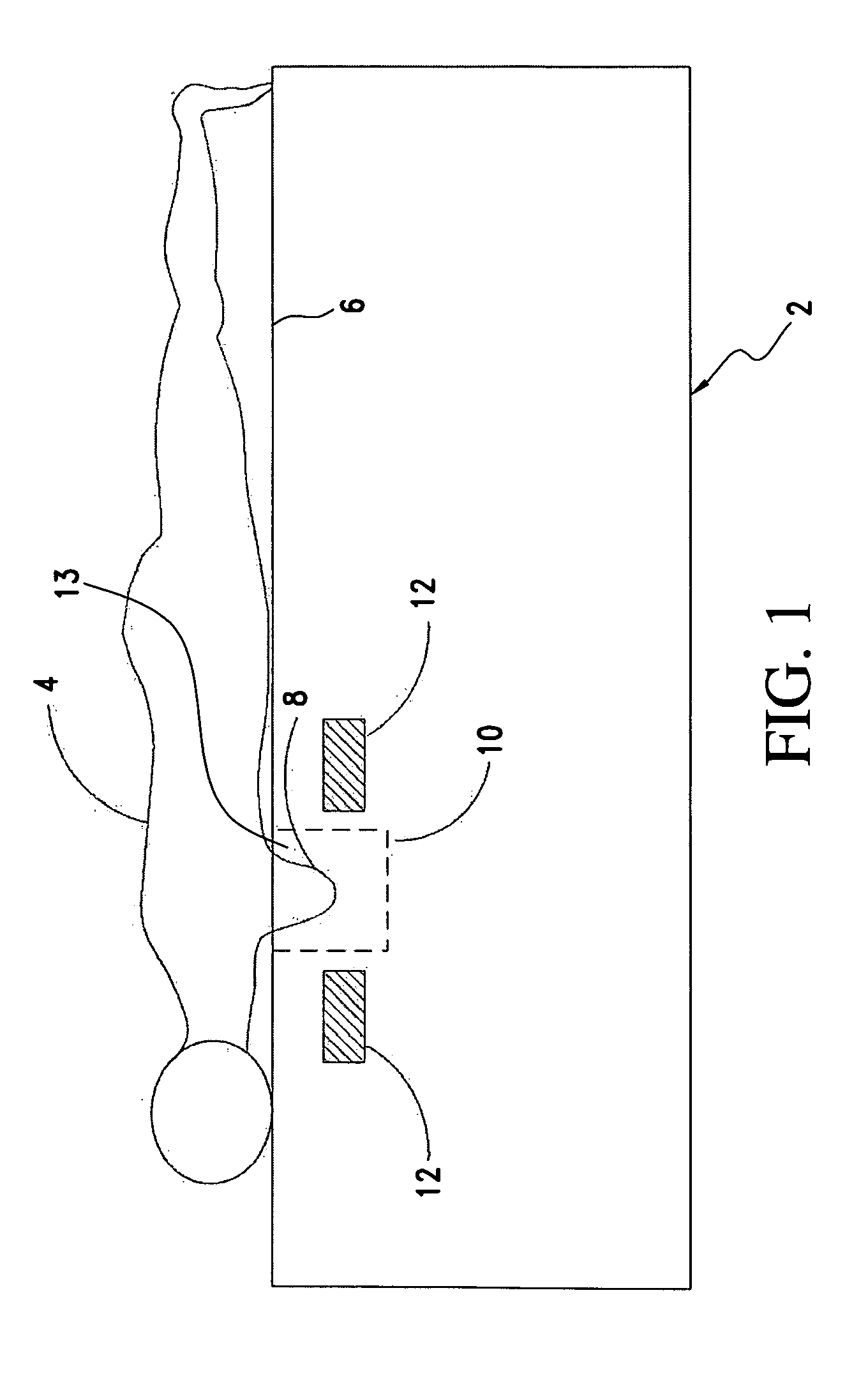
[0028] Referring to FIG. 1, an optical scanning apparatus 2, as described in U.S. Pat. Nos. 5,692,511 and 6,100,520, supports a patient 4 on a patient support surface 6, such as a tabletop. The patient's breast 8 is pendent within a scanning chamber 10, around which orbits, revolves a detector mechanism 12. The tabletop 6 includes an opening 13 through which the breast protrudes into the scanning chamber 10. The detector mechanism 12 orbits typically 360° around the vertical axis of the scanning chamber 10 and increments vertically (the “elevator” motion) between orbits to image successive slice planes. This is repeated until all the slice planes of the object have been scanned.

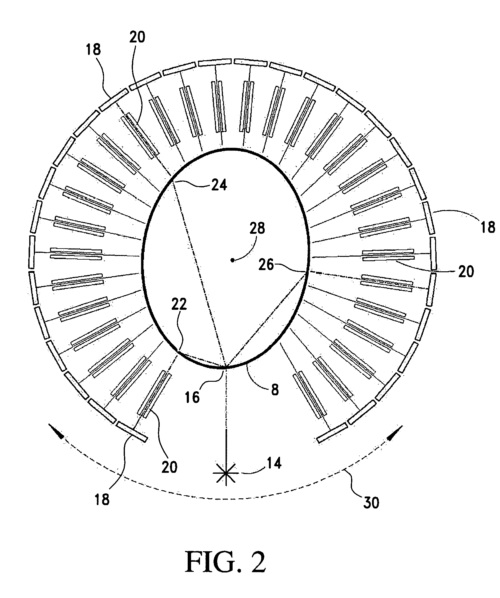
[0029]FIG. 2 shows a top view of the detector mechanism 12 from FIG. 1. A laser source 14 impinges on the scanned object, such as the breast 8 at point 16. A plurality of detectors 18 define an arc surrounding the scanned object. A collimator 20 defines each detector's field of view to a small area on the su...


PUM

PropertyMeasurementUnit
sizeaaaaaaaaaa
computed tomographic imagingaaaaaaaaaa
perimeteraaaaaaaaaa

Abstract

A diagnostic computed tomographic imaging apparatus, comprises a patient support structure including a tabletop to support a patient in front-down, prone position. The tabletop includes an opening to permit a breast of the patient to be vertically pendant below the tabletop. A scanning mechanism is disposed below the opening and orbitable about the breast pendent through the opening to obtain perimeter data and image reconstruction data of the breast. The scanning mechanism rotates about an axis of rotation transverse to the tabletop. One of the tabletop and scanning mechanism is movable in x-y axes to center the breast about the axis of rotation.

Description

RELATED APPLICATION [0001] This application claims the priority benefit of provisional application Ser. No. 60 / 759,066, filed Jan. 17, 2006.FIELD OF THE INVENTION [0002] The present invention relates to a diagnostic optical imaging apparatus that employs a near-infrared laser as a radiation source and a detector array with restricted fields of view directed to their own patches of surface of the object being scanned to simultaneously detect the intensity of light exiting from the object for the purpose of reconstructing optical cross-sectional images of that object, and particularly where the object is movable relative to the radiation source and the detector array thereby to center the object about the scanning mechanism. BACKGROUND OF THE INVENTION [0003] Cancer of the breast is a major cause of death among the American female population. Effective treatment of this disease is most readily accomplished following early detection of malignant tumors. Major efforts are presently unde...

Claims


Application Information

Patent Timeline
Patent Type & Authority Applications(United States)
IPC IPC(8): G01N23/04H05G1/02A61B5/05
CPCA61B5/0091A61B6/027A61B5/4312
Inventor JONES, SHARON D.SALIT, EMILY A.WAKE, ROBERT H.MAGRANER, VINCENTEMOYA, RICHARD A.
Owner IMAGING DIAGNOSTIC SYST
Why Eureka
Try Eureka