Container Welding Method

a technology of welding method and container, which is applied in the direction of wrapping, twisting/gathering wrappers, transportation packaging, etc., can solve the problems of not being able to use the internal mandrel, complex mechanical means for exerting such a force or pressure on the periphery of the tube, and affecting the product quality of the product, so as to improve the diameter, improve the barrier properties, and the effect of effective and elegan

Inactive Publication Date: 2007-10-18
AISAPACK HLDG SA
View PDF17 Cites 7 Cited by
  • Summary
  • Abstract
  • Description
  • Claims
  • Application Information

AI Technical Summary

Benefits of technology

[0009] An object of the present invention is to propose a method for manufacturing flexible containers that makes it possible to seal a plastic piece having a slightly concave form to an end of a hollow plastic body without using a mandrel inside the hollow body. The method according to the invention proposes a very simple way in which to generate the pressure needed for welding without the use of an internal mandrel.
[0010] The present invention thus makes it possible to manufacture articles such as in FIGS. 1, 2 and 3, thereby solving the abovementioned problem.
[0011] For simplification's sake, but not exhaustively, the description and the examples given below will be restricted to the case of welding heads and bases on tube made from laminated material containing a thin aluminum sheet. This aluminum sheet inside the structure of the layers of the composite material confers excellent barrier properties on the packaging and at the same time allows the use of HF heating technology, which is very effective and elegant. This tube is produced from a multi-layer flat sheet or strip containing at least one aluminum layer and including a longitudinal lap weld. Induction heating is also used for welding the head or base. The absence of mechanical means for producing the bearing force and the welding pressure renders the application of induction-welding technology particularly suitable, since the HF inductor can be placed very close to the area to be welded, eliminating the problem of shielding the mechanical piece.
[0012] The method according to the invention is based on the fact that the pressure needed for welding the head or the semirigid base to the skirt is obtained by the temporary or permanent deformation of the semirigid piece. By deforming this piece in a controlled manner, it is possible to increase its diameter and thus the piece rests on the skirt and on a welding tool placed on the outside of the skirt. It is thus possible to produce uniform pressure over the entire area to be sealed.

Problems solved by technology

The mechanical means for exerting such a force or pressure on the periphery of the tube are complex, prevent or disrupt the transfer of heat, and leave traces of parting lines on the product.
However, it is much less obvious to seal an end to tube whose other end is partially or totally closed, as it is no longer possible to use the internal mandrel.

Method used


Image

  • Container Welding Method
  • Container Welding Method
  • Container Welding Method

Examples


Embodiment Construction

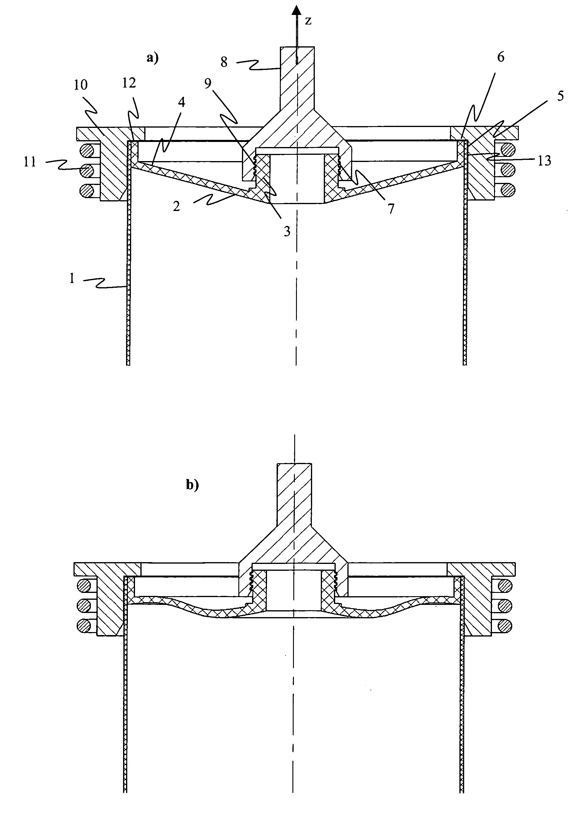
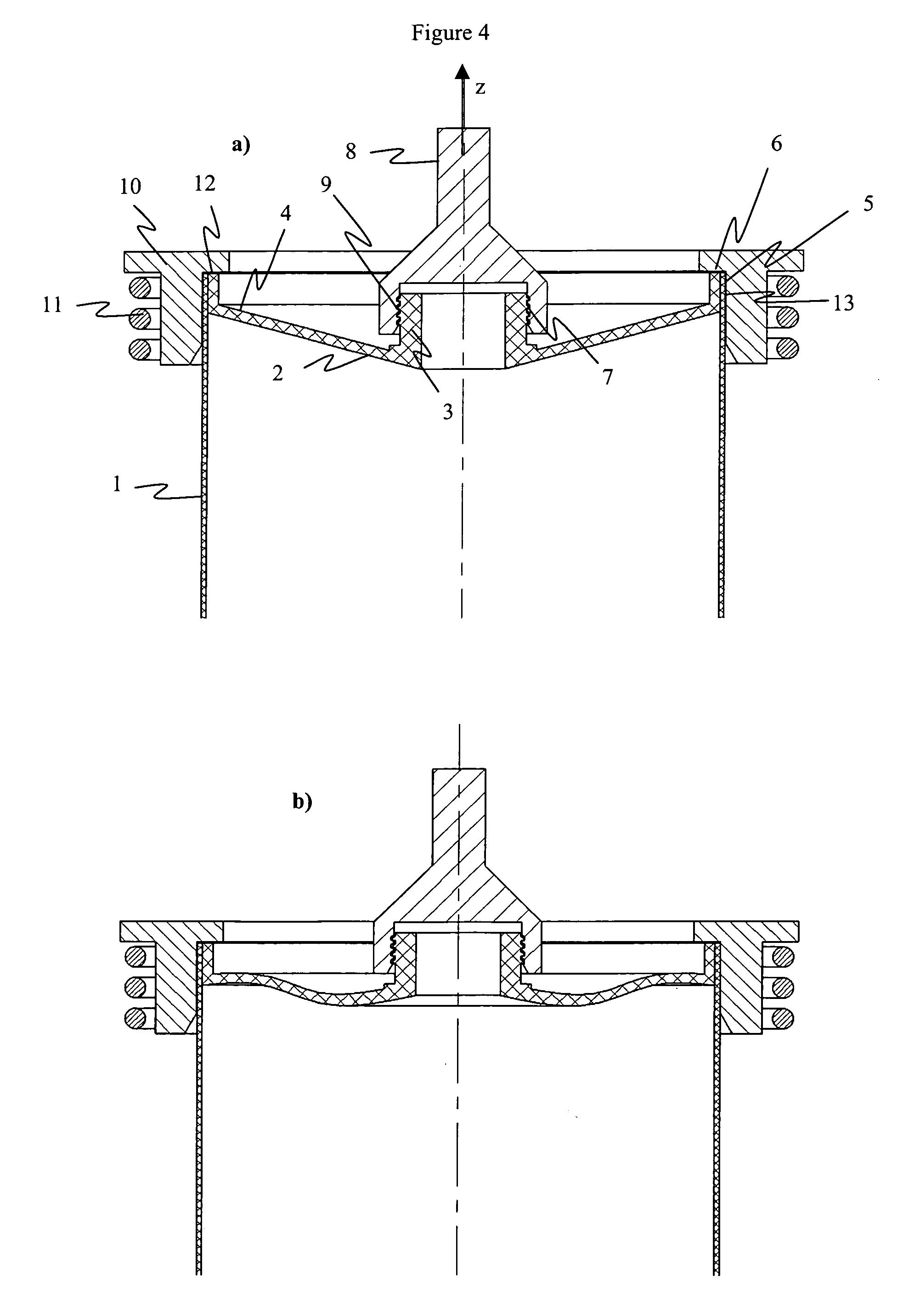
[0020] The principle of the method according to the invention is clearly explained by means of a definition of the various steps in the method, presented in FIGS. 4a and 4b :

[0021] 1) The tube skirt 1 and the head have to be positioned precisely inside a welding tool 10, as shown in FIG. 4a. This welding tool 10 has to cover the area to be sealed and also guide the skirt 2. This tool includes a perpendicular area 12 allowing the skirt 1 and the head 2 to rest thereon in the direction Z.

[0022] 2) A connecting rod 8 is attached to the neck of the head 3. The two pieces may be held in different ways, for example by screwing an internal thread 9 on the thread of the neck 7.

[0023] 3) A tensile force is exerted by the rod 8 on the head 2 in the direction Z. As the head is held in place by the welding tool 10 in the support area 12, the result is that the head 2 will be deformed, as shown in FIG. 4b, owing to its slightly concave shape, if it is made from semirigid material. Deformation...


PUM

PropertyMeasurementUnit
flexibleaaaaaaaaaa
tensile forceaaaaaaaaaa
radial forcesaaaaaaaaaa

Abstract

The invention relates to a method for manufacturing a plastic container, comprising the edge-clamping of a flat, flexible piece forming a curved surface over the inner face of a hollow body, characterized in that the following steps are performed: the edge of the piece is placed in contact with the inner face of the hollow body; a thrust or tensile force is applied to the piece in a direction perpendicular to its surface such as to induce in the piece radial forces resulting in a bringing-together of the edge of the piece against the inner face of the hollow body.

Description

FIELD OF THE INVENTION [0001] The present invention relates to a method for manufacturing containers that makes it possible to weld a semirigid plastic piece having a slightly concave form to an end of a hollow plastic body. [0002] The present invention is intended in particular, but not exclusively, for the field of packaging for non-carbonated food-grade beverages, such as fruit juices, vitamin drinks, milk, iced tea, etc. [0003] Another field of application of the present invention is that of flexible plastic tube for packaging viscous products, such as toothpaste, body-care crèmes, pharmaceutical ointments, food products (mayonnaise, ketchup, mustard), etc. [0004] A third area of application of the present invention is that of cartridges for technical products, such as silicone or mastic. Prior Art [0005] The production of containers provided with a semirigid piece sealed to a hollow plastic body of principally cylindrical form is a technology frequently used in the manufacture ...

Claims


Application Information

Patent Timeline
Patent Type & Authority Applications(United States)
IPC IPC(8): B29C65/02B29C65/00
CPCB29C66/24223B29C66/2424B29C66/24245B29C66/24249B29C66/612B29C66/826B29L2023/20B29C65/00B29C65/08B29C65/10B29C65/06B29C65/1412B29C65/02B29C66/63B29L2031/712B29C65/3656B29C65/368B29C66/112B29C66/1122B29C66/131B29C66/5344B29C66/542B29C66/543B29C66/72321B29C66/851B29K2705/02
Inventor KELLER, GERHARDROY, HUGUES-VINCENTTHOMASSET, JACQUES
Owner AISAPACK HLDG SA
Why Eureka
Try Eureka