Intake device for outboard motors

a technology for intake devices and outboard motors, which is applied in the direction of machines/engines, combustion air/fuel air treatment, and feed systems, etc. it can solve the problems of reducing the intake performance of outboard motors, increasing the size of devices, and unable to provide funnel-shaped members, etc., to achieve the effect of improving intake performance and reducing the size of devices

Active Publication Date: 2007-10-18
SUZUKI MOTOR CORP
View PDF0 Cites 2 Cited by
  • Summary
  • Abstract
  • Description
  • Claims
  • Application Information

AI Technical Summary

Benefits of technology

[0012] The present invention provides an intake device for outboard motors, which makes it possible to improve intake performance and reduce the size of the device at the same time.

Problems solved by technology

However, the conventional intake device, which is provided with two surge tanks, needs a complicated construction, which inevitably increases the size of the device.
Further, it is required to form a bend in an intermediate portion of an intake passage member connecting between each surge tank and an associated cylinder head, and the bend causes intake air resistance, which leads to degradation of the intake performance of the outboard motor.
However, an intake device for outboard motors, provided with the throttle valve disclosed in Japanese Laid-Open Patent Publication (Kokai) No. 2004-232591 suffers from a problem that it is difficult to secure a sufficient capacity of a surge tank due to the construction of an outboard motor, and hence, when a sufficient capacity of a surge tank cannot be secured, it is impossible to provide the funnel-shaped members.
However, the problem concerning the size of the intake device cannot be solved by simply changing the mechanical throttle body to the electronically-controlled throttle body.
In addition, the conventional intake devices have a silencer mounted to the end of an intake port of the throttle body in a protruding manner, which causes further increase in the size of the intake device.
As described above, the conventional intake devices for outboard motors cannot avoid increase in device size or degradation of intake performance.

Method used


Image

  • Intake device for outboard motors
  • Intake device for outboard motors
  • Intake device for outboard motors

Examples


Embodiment Construction

[0048] The present invention will now be described in detail below with reference to the drawings showing preferred embodiments thereof.

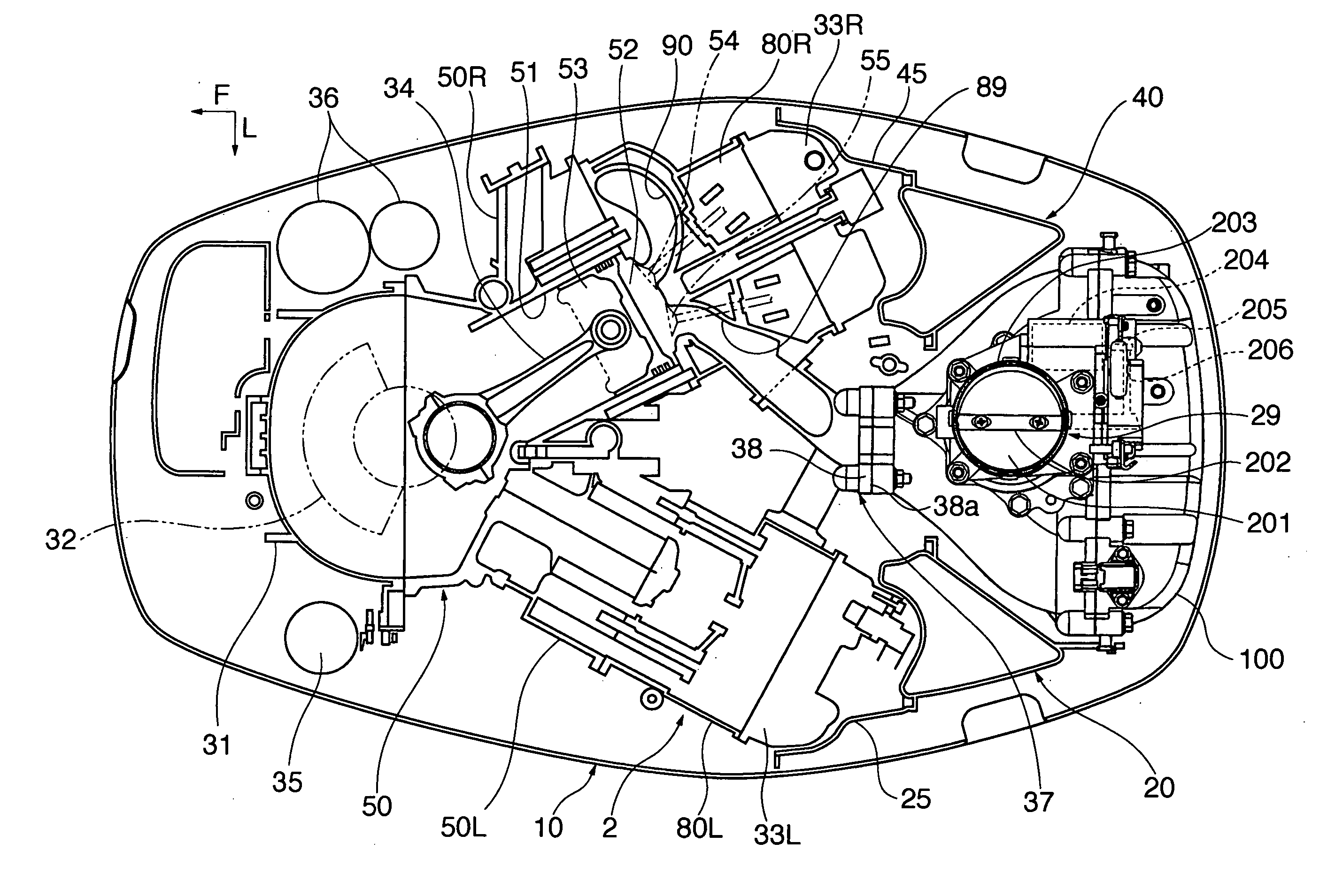
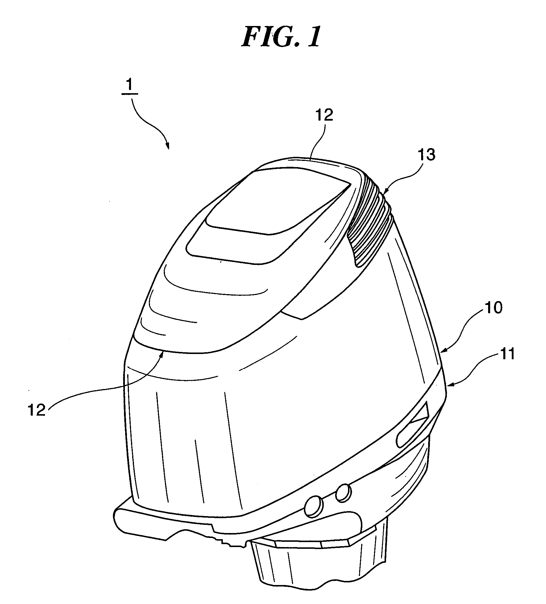
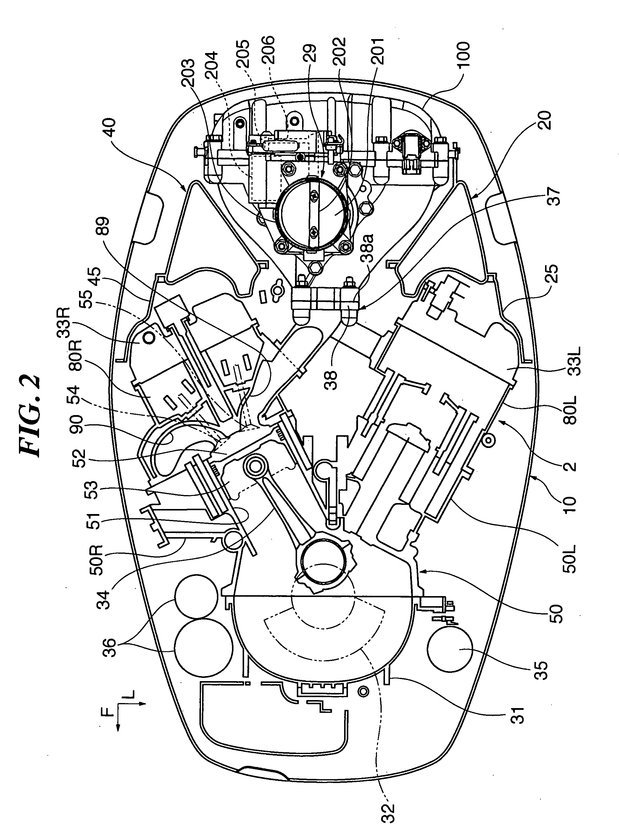
[0049]FIG. 1 is a perspective view of an upper half of an outboard motor 1 equipped with an intake device according to an embodiment of the present invention. FIG. 2 is a partial cross-sectional view of the outboard motor 1 as viewed in the horizontal direction. It should be noted that, as shown in FIG. 2, arrows F and L indicate a forward or bow direction and a port direction, as viewed on the outboard motor 1, respectively.

[0050] The outboard motor 1 is equipped with an engine 2, described in detail hereinafter. The engine 2 is a water-cooled four-cycle six-cylinder V-type engine having a crankshaft 32 substantially perpendicularly (vertically) installed therein and a cylinder block 50 integrally formed with a pair of left and right cylinder banks disposed in a V-shaped arrangement in plan view to form a rearwardly open V-shaped cylinder bank (V...


PUM


Abstract

An intake device for outboard motors, which makes it possible to improve intake performance and reduce the size of the device at the same time. Cylinder banks have a plurality of cylinder bores arranged in a vertical direction, and extend rearward to form a V shape. Intake ports of the respective cylinder bores are formed in the cylinder banks to open in the inner sides of the V shape. An intake manifold is connected to the intake ports. A surge tank is connected to the intake manifold. A throttle body is connected to the surge tank. The surge tank comprises a plurality of intake passage members connected to the respective cylinder bores via the intake manifold, wall members provided between respective adjacent ones of the intake passage members, and a lid member configured to hermetically close a space defined by the intake passage members and the wall members.

Description

BACKGROUND OF THE INVENTION [0001] 1. Field of the Invention [0002] The present invention relates to an intake device for outboard motors, and more particularly to an intake device for outboard motors equipped with a V-type engine for vertical installation. [0003] 2. Description of the Related Art [0004] Conventionally, a general type of intake device for outboard motors equipped with a V-type engine has surge tanks provided for respective cylinder banks (see e.g. Japanese Laid-Open Patent Publications (Kokai) No. H09-42088 and No. 2002-242777). However, the conventional intake device, which is provided with two surge tanks, needs a complicated construction, which inevitably increases the size of the device. Further, it is required to form a bend in an intermediate portion of an intake passage member connecting between each surge tank and an associated cylinder head, and the bend causes intake air resistance, which leads to degradation of the intake performance of the outboard motor...

Claims


Application Information

Patent Timeline
Patent Type & Authority Applications(United States)
IPC IPC(8): F02D11/10F02M35/10
CPCF02M35/10032F02M35/167F02M35/116F02M35/10039
Inventor MIYASHITA, YASUSHITAKEWAKI, HIROMICHIITO, JUNKOYAMA, HIDEO
Owner SUZUKI MOTOR CORP
Why Eureka
Try Eureka