

Pneumatic Tire
a technology of pneumatic tires and grooves, which is applied in the direction of non-skid devices, vehicle components, transportation and packaging, etc., can solve the problems of easy clogging of grooves, lowering of snow performance, and difficult to discharge snow from grooves, so as to improve snow performance and mud performance, the effect of not causing clogging of the groov
- Summary
- Abstract
- Description
- Claims
- Application Information
AI Technical Summary
Benefits of technology
Problems solved by technology
Method used
Image

Examples
first embodiment
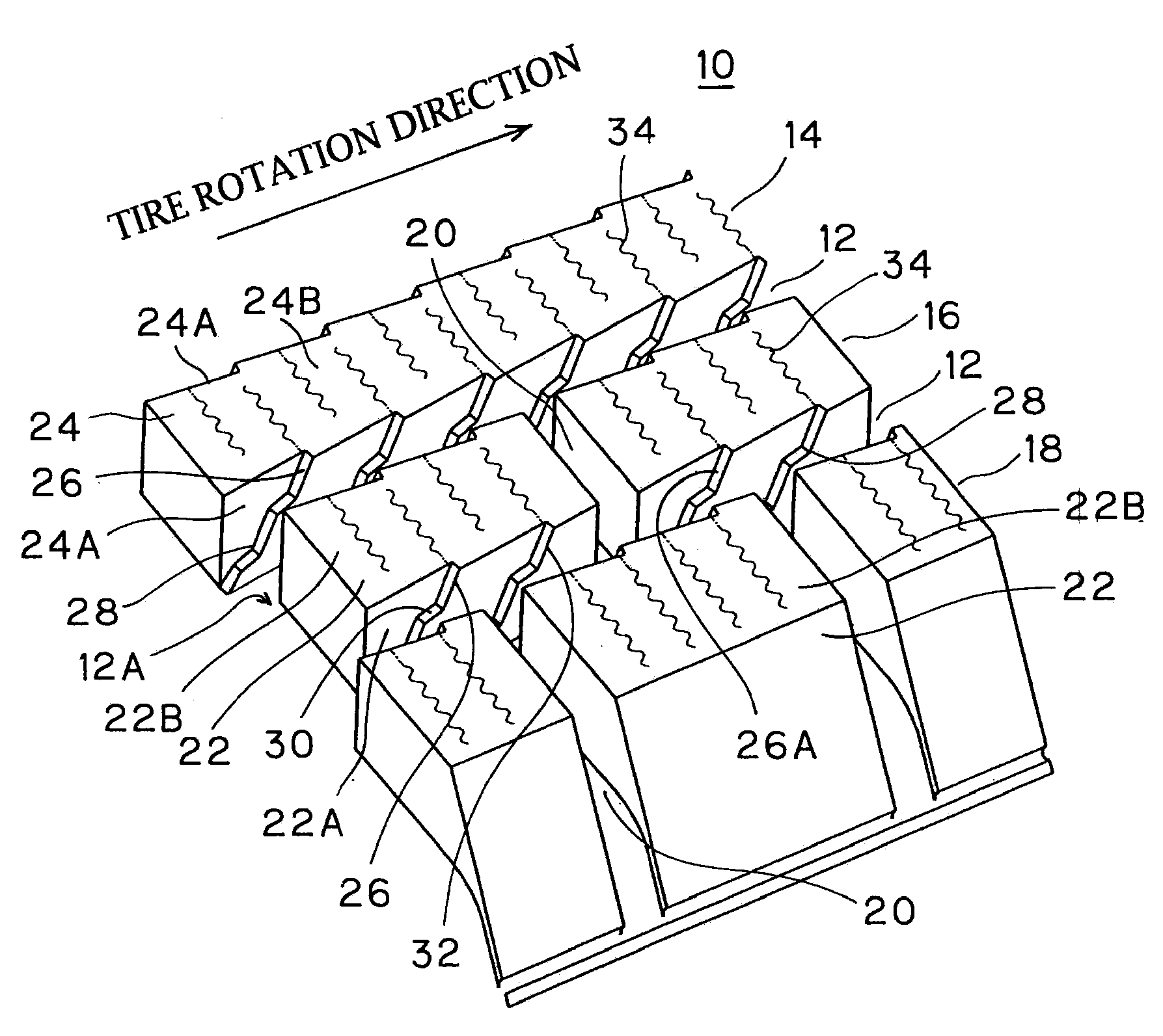
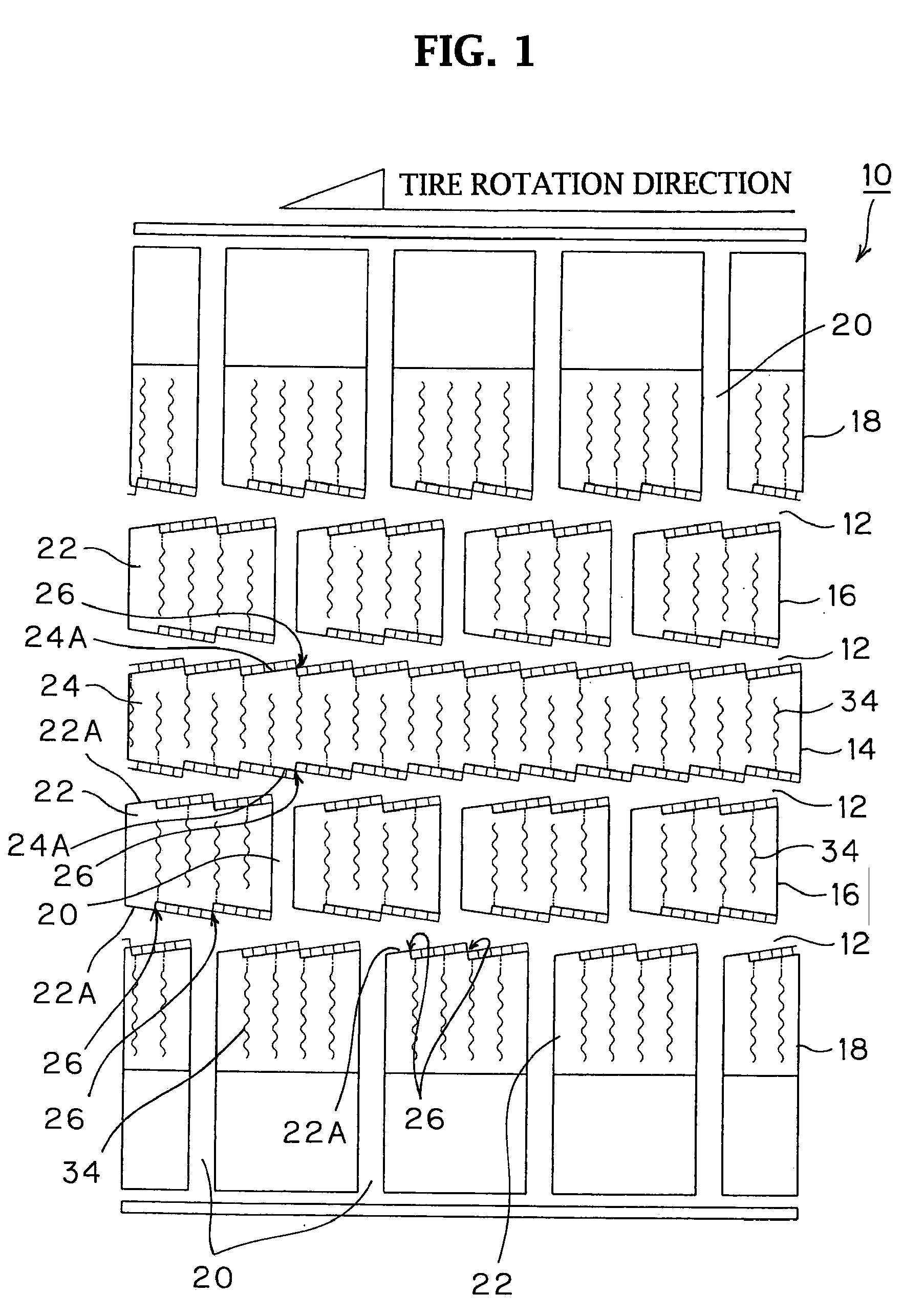
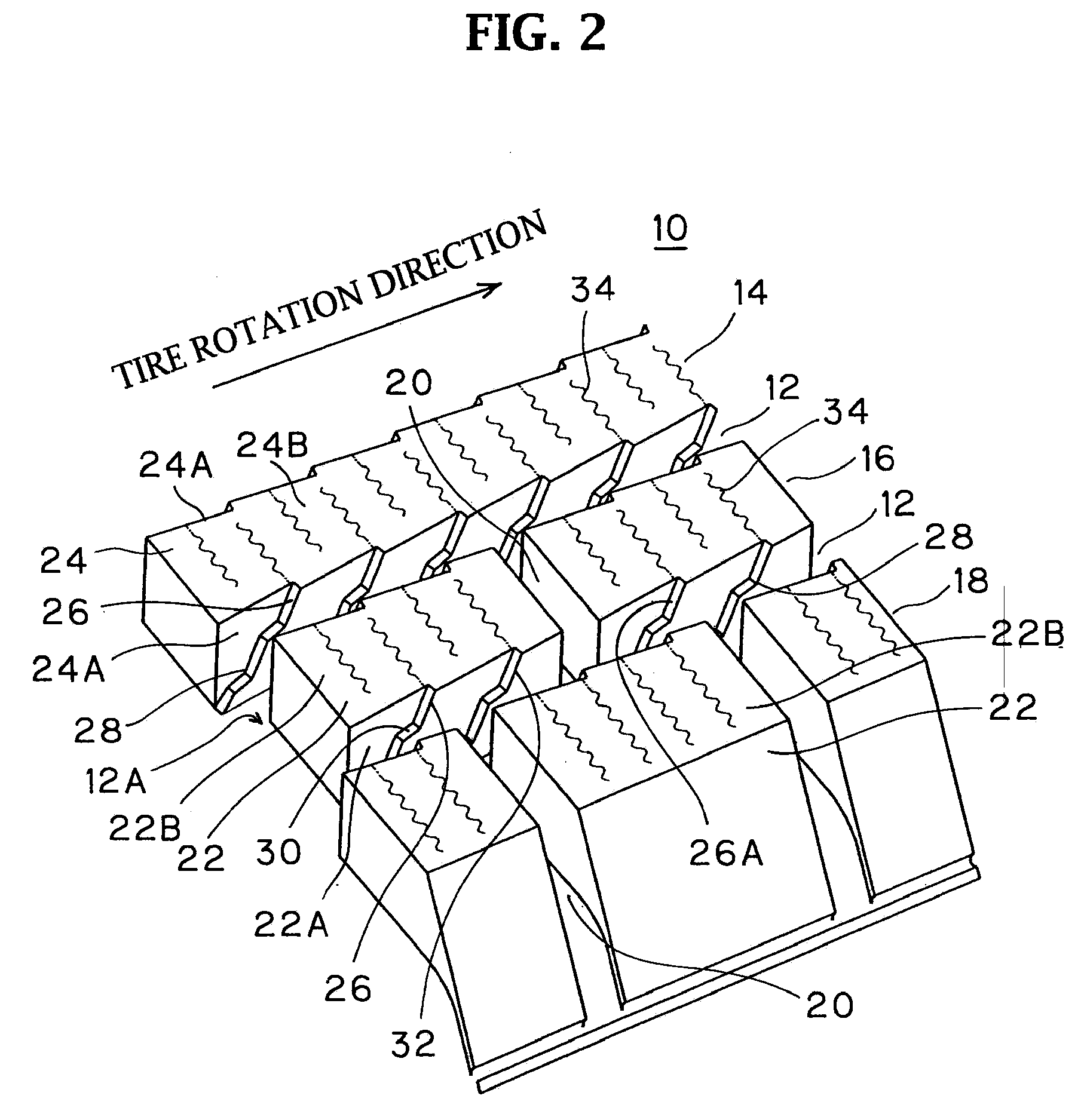
[0027]FIG. 1 is a plan view illustrating a part of a developed tread pattern of a pneumatic tire (studless tire) in a first embodiment according to the invention. FIG. 2 is an enlarged perspective view illustrating a part of the tread shown in FIG. 1. The tire has a plurality of circumferential grooves 12 extending in a tread circumferential direction (the number of the grooves 12 is four in this embodiment) on a tread 10. The circumferential grooves 12 divide the tread 10 into five regions of a center region 14, intermediate regions 16, 16 provided on both sides of the center region 14 such that the center region 14 is sandwiched between the intermediate regions 16, 16, and shoulder regions 18, 18 formed at both ends of the tread 10 outside the intermediate regions 16.
[0028]The intermediate regions 16 and the shoulder regions 18 have transverse grooves 20 arranged in parallel at predetermined intervals in the circumferential direction. The transverse grooves 20 extend in the tread ...
second embodiment
[0035]FIG. 5 is a block structure according to a second embodiment. In this embodiment, the edges 26 having a similar step-shaped structure as that of the edges 26 in the first embodiment are formed on all the sides of the blocks 22 such that all the sides have zigzag shapes.
[0036]Since the edges 26 are formed not only on the sides 22A facing the circumferential grooves 12 but also on sides 22C facing the transverse grooves 20, clogging of the transverse grooves 20 by snow or mud can be further prevented.
[0037]According to this embodiment, the edges 26 and the inclination of the step shapes of the edges 26 formed on the left side 22A facing the corresponding circumferential groove 12 are opposite to those on the right side 22A facing the corresponding circumferential groove 12. This structure is applicable to a tire whose rotation direction is not fixed. Similarly, the edges 26 and the inclination of the step shapes of the edges 26 formed on the front side 22C facing the correspondi...
third embodiment
[0039]FIG. 6 is a block structure according to a third embodiment. In this embodiment, the step-shaped edges 26 have round and wavy shapes with no corners, unlike the cornered shapes in the first embodiment.
[0040]According to this embodiment, the edges 26 have bent portions 28 (curved portions) curved such that obtuse angles are formed, and thus the edges 26 have wavy step shapes in the depth direction of the grooves 12 as viewed from the block sides 22A as the front surfaces. The obtuse angles of the curved portions 28 herein refer to obtuse angles formed by linear portions when the linear portions are present above and below the curved portions 28, and obtuse angles formed by tangential lines of curvilinear portions above and below the curved portions 28 when the linear portions are not present.
[0041]Other parts are similar to those in the first embodiment. Similarly to the above embodiments, snow or mud having entered the grooves 12 easily moves due to the presence of the curved ...
PUM
 Abstract
Description
Claims
Application Information