Tire mounting lever having a curved mounting surface

a technology of mounting lever and tire, which is applied in the field of tire mounting levers, can solve the problems of not realizing form closure, and achieve the effects of avoiding excessive tension, reducing tire heel pressure, and avoiding damage when dismantling tires even more reliably

Inactive Publication Date: 2007-10-18
BEISSBARTH
View PDF7 Cites 5 Cited by
  • Summary
  • Abstract
  • Description
  • Claims
  • Application Information

AI Technical Summary

Benefits of technology

[0006] According to a basic idea of the invention a mounting lever is appropriately profiled such that it comprises a convex mounting surface, which is capable in its use to avoid excessive tensions between mounting lever and heel of the tire. Thus damages when dismantling the tires are prevented. Such a mounting lever is suitable for the damageless dismantling of tires, especially of tires having a reinforced side wall. Cuts and pressure marks in the heel of tire which result from the use of commercially available mounting levers at the upper edges of the mounting lever due to strong punctiform stress are thereby reliably avoided. With conventional mounting levers, the heel of the tire rests with very low pressure between the corner points of the mounting lever, and no real form closure is accomplished. This effect does not depend in the first instance from the material strength of the used mounting lever, but rather mainly from

Problems solved by technology

With conventional mounting levers, the heel of the tire rests with very low pressure be

Method used


Image

  • Tire mounting lever having a curved mounting surface
  • Tire mounting lever having a curved mounting surface
  • Tire mounting lever having a curved mounting surface

Examples


Embodiment Construction

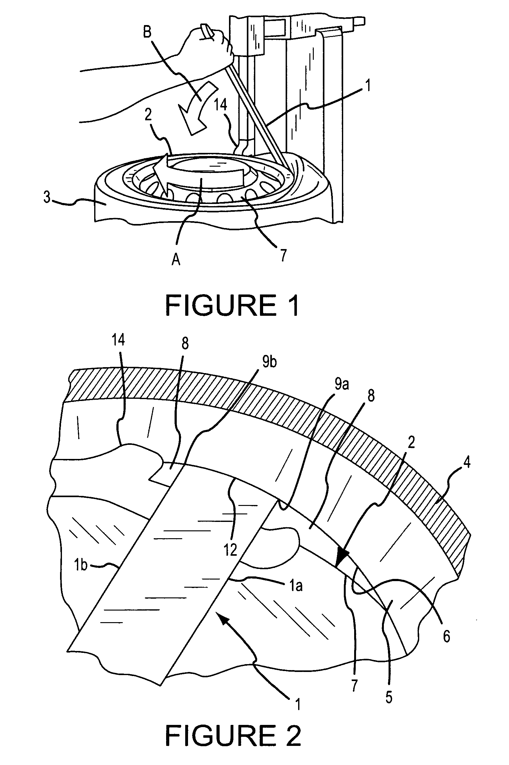
[0022] As shown in FIG. 1, a disk machine is being used to dismantle a tire 3 from a rim 2 using a mounting lever 1. Such disk machines are known to the person skilled in the art. The tire 3 is clamped onto a rotatable disk (not shown in FIG. 1) on which the tire 3 is placed. The disk machine includes a mounting head 14 having a gibbet.

[0023] To remove the tire 3 from the rim 2, the front end of the mounting lever 1 is inserted between the rim 2 and the tire 3. In doing so it is necessary for the tire 3 to rest in the base rim at the opposite side of the mounting head 14. The tire 3 is subsequently lifted over the mounting head 14 by lowering the back end of the mounting lever 1 in the direction of the arrow B, such that it sits between the heel of the tire and a flange 7 of the wheel. After pulling out the mounting lever 1 down, the disk is rotated with the rim 2 in the direction of the arrow A to remove the tire 3 from the rim 2.

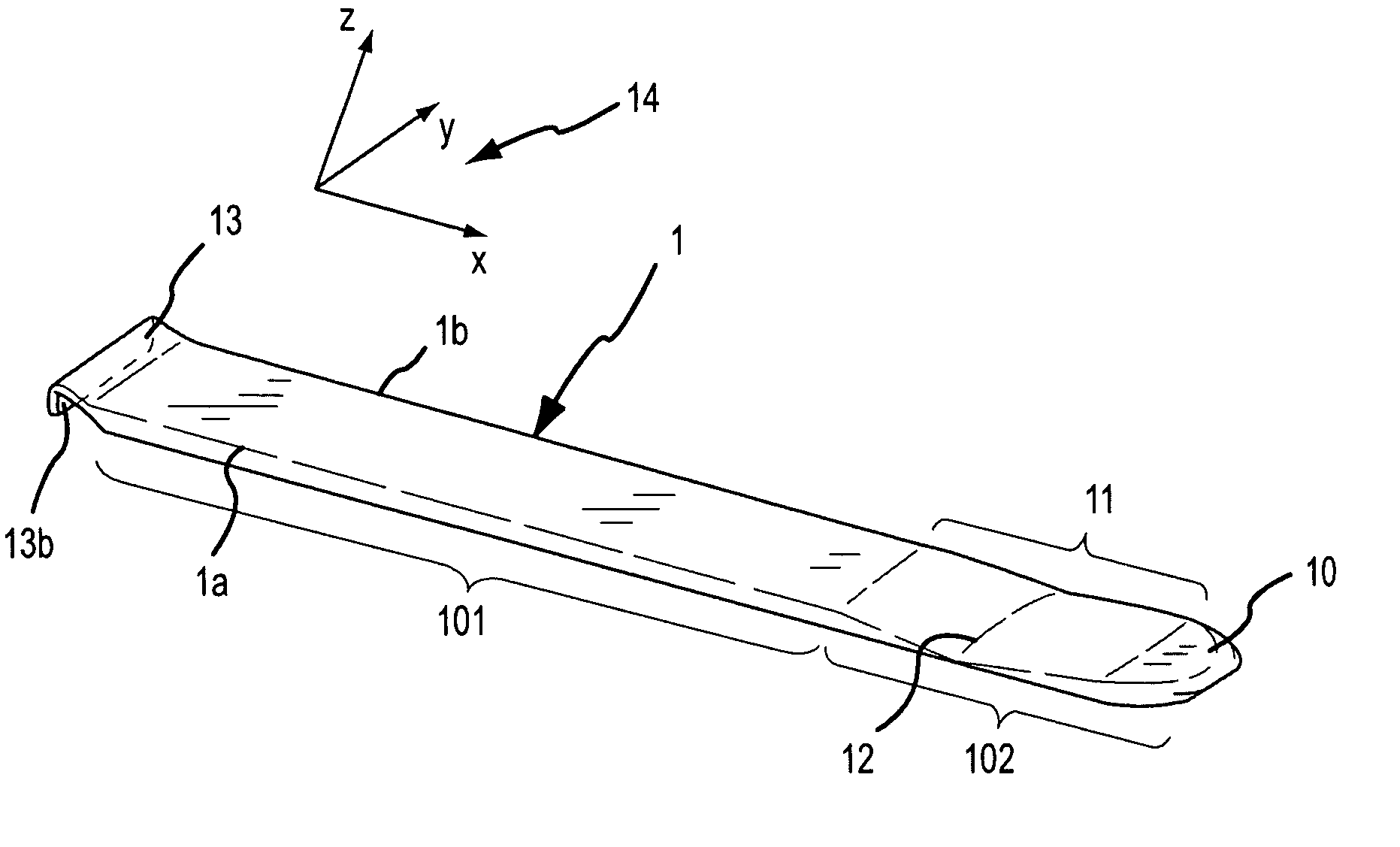
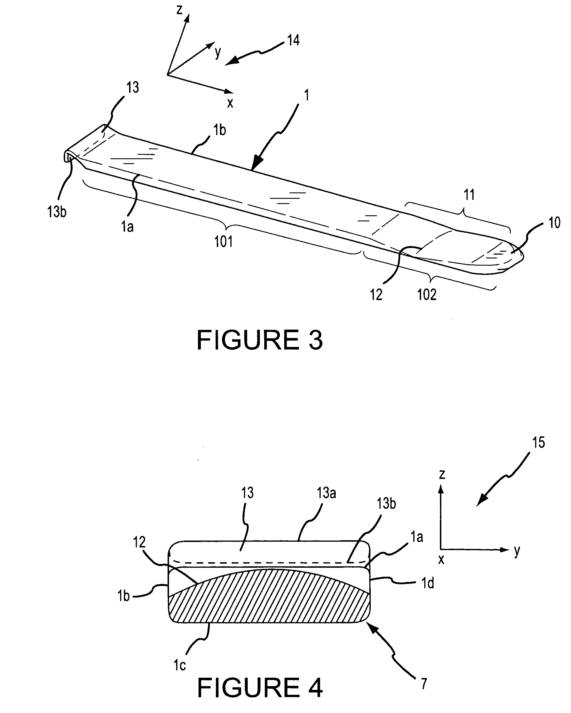
[0024] The manner in which the mounting lever 1 en...


PUM


Abstract

A mounting lever (1) according to one embodiment of the invention for dismantling a vehicle tire from a rim comprises a rod-formed handle portion (101) and a work portion (102) provided at its front end. The work portion (102) has a convex mounting surface (11).

Description

TECHNICAL FIELD [0001] The invention relates to a mounting lever for vehicle tires. BACKGROUND OF THE INVENTION [0002] Modern tires with emergency running properties have a reinforced tire wall and are used with rims comprising so called “extended humps.” Such tires must, on the one hand, carry at least a fourth of the vehicle weight, and may, on the other hand, not hop from the rim when driving with tire pressure that is too low. [0003] To dismantle such tire from a rim, the tire is often claimed onto a disk machine. By use of a mounting lever, the heel of the tire is moved from the rim over a mounting head positioned at the wheel flange, which subsequently removes the tire from the rim supported by the rotational movement of the disk. To dismantle such tire from the rim, the heel of the tire must be pushed outwards with a force of approximately 600 N. With the commercially available mounting levers e.g. with the mounting lever known from the German Utility Model G 92 11 934.4, the...

Claims


Application Information

Patent Timeline
IPC IPC(8): B60C25/04
CPCB60C25/04
Inventor WERNER, OLIVER
Owner BEISSBARTH
Why Eureka
Try Eureka