Vehicle and control method of vehicle

a technology of vehicle and control method, which is applied in the direction of braking system, battery/fuel cell control arrangement, braking components, etc., can solve the problems of response delay, failure to satisfy the driver's braking force, and requires some time, and achieve the effect of reducing the regenerative braking for

Active Publication Date: 2007-10-18
TOYOTA JIDOSHA KK +1
View PDF10 Cites 58 Cited by
  • Summary
  • Abstract
  • Description
  • Claims
  • Application Information

AI Technical Summary

Benefits of technology

[0020]In the control method of the vehicle of the invention, after the preliminary operation control of the pressurization unit to exert its proper pressurization performance, the substantial replacement operation is performed to replace the regenerative braking force output from the motor with the pressure increase-based braking force based on the pressure increase by the pressurization unit. This enables smooth replacement of the regenerative braking force of the motor with the braking force ...

Problems solved by technology

The hydraulic braking system equipped with a brake actuator of relatively simple structure that does not have an accumulator or pressure reservoir generally has a response delay and requires some time to obtain a desired response after the start of actuation.
Failed replacement of the regenerative braking force with the braking force of the hydraulic braking system may cause failed output of a braking force satisfying the driver's demand and make the driver feel uneasy and uncomfortable.
The hydraulic brak...

Method used


Image

  • Vehicle and control method of vehicle
  • Vehicle and control method of vehicle
  • Vehicle and control method of vehicle

Examples


first embodiment

A. First Embodiment

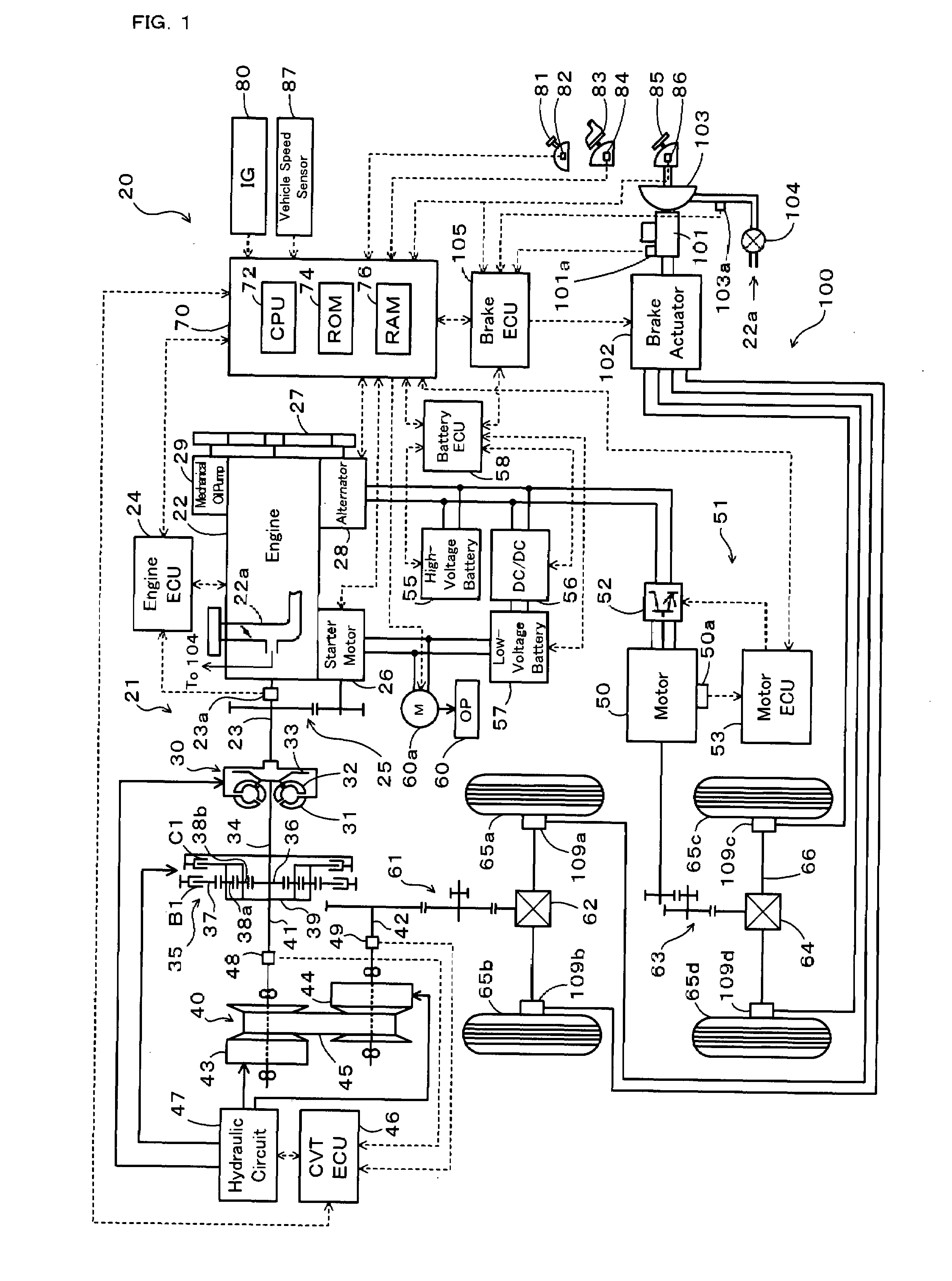
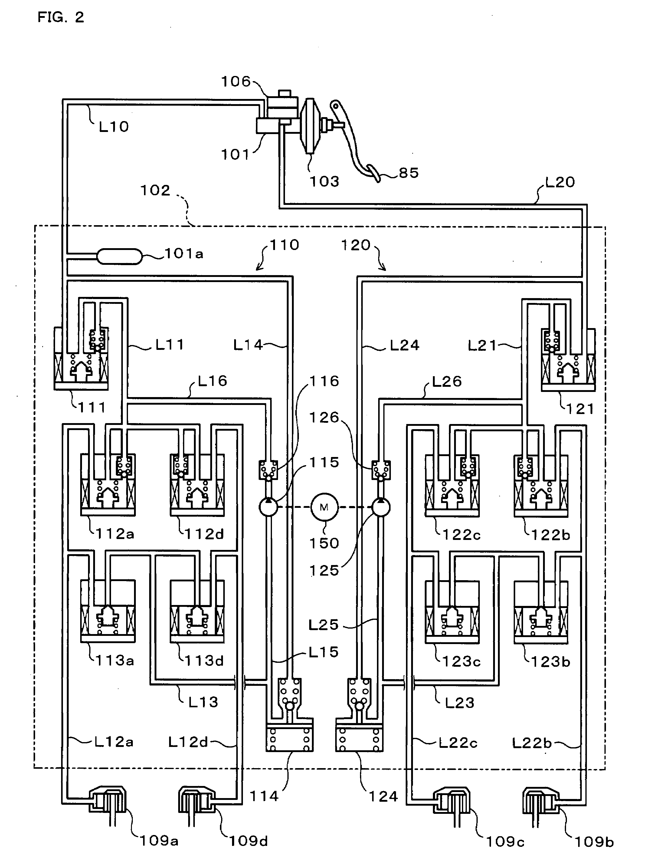
[0037]FIG. 1 schematically illustrates the configuration of a hybrid vehicle 20 in a first embodiment of the invention. The hybrid vehicle 20 of the embodiment has a front wheel driving system 21 for transmission of output power of an engine 22 to front wheels 65a and 65b via a torque converter 30, a forward-backward drive switchover mechanism 35, a belt-driven continuously variable transmission (hereafter referred to as ‘CVT’) 40, a gear mechanism 61, and a differential gear 62, a rear wheel driving system 51 for transmission of output power of a motor 50 to rear wheels 65c and 65d via a gear mechanism 63, a differential gear 64, and a rear axle 66, an electronically controlled hydraulic braking system (hereafter referred to as ‘HBS’) 100 for application of braking force to the front wheels 65a and 65b and to the rear wheels 65c and 65d, and a hybrid electronic control unit (hereafter referred to as ‘hybrid ECU’) 70 for controlling the operations of the whole hyb...

second embodiment

B. Second Embodiment

[0064]A second embodiment of the invention is described below.

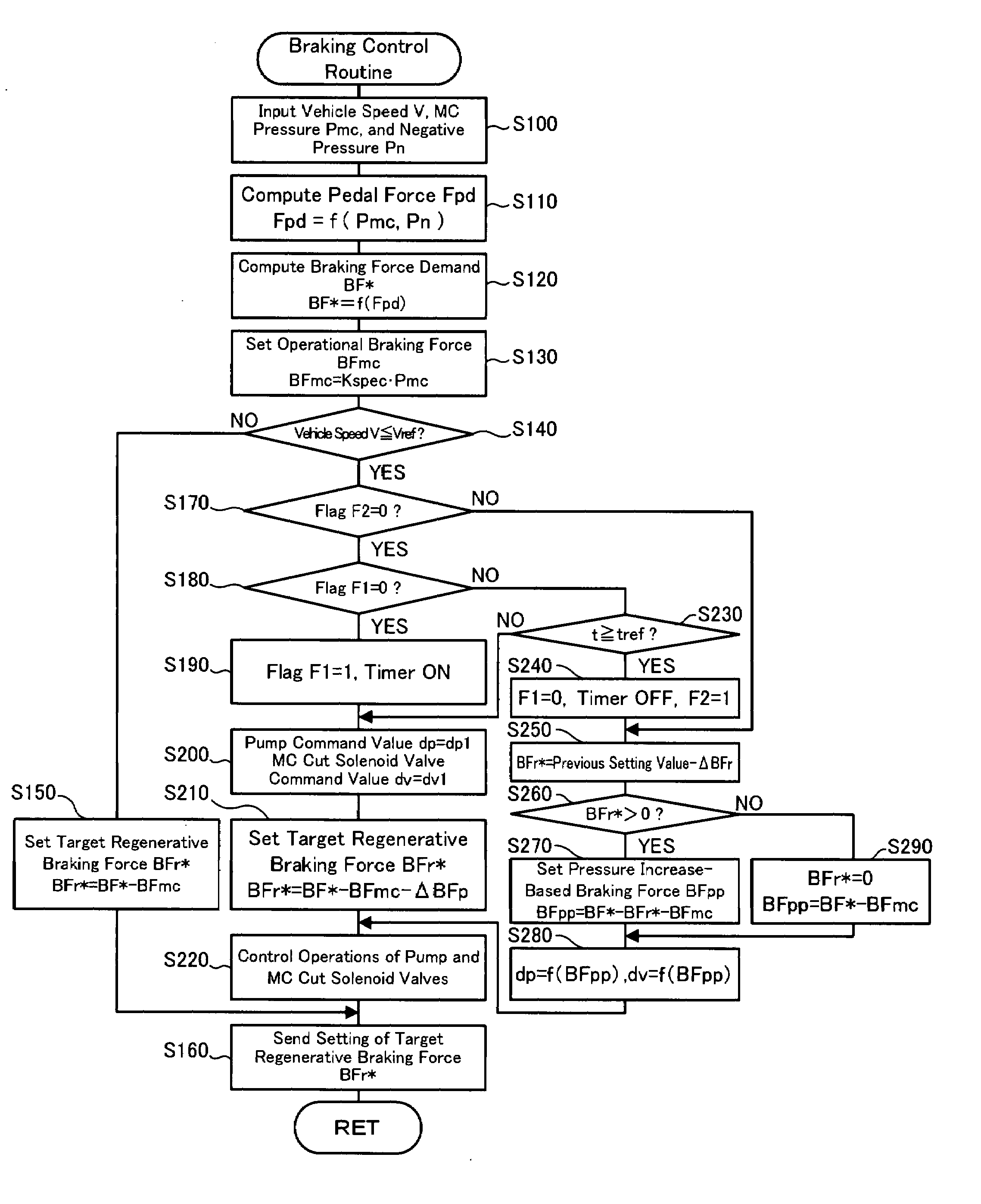
[0065]FIG. 7 is a flowchart showing another braking control routine that may be executed by the hybrid vehicle 20 described above. This braking control routine is also repeatedly executed at preset time intervals to satisfy a braking force demand by the sum of the master cylinder pressure Pmc-based braking force and the regenerative braking force of the motor 50 when the driver depresses the brake pedal 85.

[0066]On the start of the braking control routine shown in FIG. 7, a CPU (not shown) of the brake ECU 105 inputs required data for control, that is, the vehicle speed V from the vehicle speed sensor 87, the master cylinder pressure Pmc from the master cylinder pressure sensor 101a, the negative pressure Pn from the pressure sensor 103a, the gearshift position Sp from the gearshift position sensor 82, and the setting of a regeneration prohibition flag Fr (step S300). The regeneration prohibition flag ...


PUM


Abstract

When vehicle speed V decreases to or below a preset reference vehicle speed Vref during output of regenerative braking force from a motor in response to the driver's depression of a brake pedal, the vehicle of the invention performs a replacement pre-operation (steps S190 to S220 and S160) and a replacement operation (steps S240 to S280 and S160) and controls the motor and an electronically controlled hydraulic braking system to satisfy a braking force demand BF*. The replacement pre-operation actuates and controls pumps included in a brake actuator of the electronically controlled hydraulic braking system to exert their proper pressurization performance. The replacement operation decreases the regenerative braking force output from the motor and enhances a pressure increase by the pumps to replace the regenerative braking force with a pressure increase-based braking force BFpp.

Description

BACKGROUND OF THE INVENTION[0001]1. Field of the Invention[0002]The present invention relates to a vehicle and a control method of the vehicle. More specifically the invention pertains to a vehicle equipped with a motor that is capable of outputting regenerative braking force, as well as to a corresponding control method of such a vehicle.[0003]2. Description of the Related Art[0004]In one proposed structure of an electric vehicle, an electric motor in an electric driving system is used to rotate drive wheels both in a normal direction and in a reverse direction. When the vehicle speed exceeds a preset reference vehicle speed at the timing of the driver's depression of a brake pedal, the electric vehicle of this structure performs regenerative braking control (see, for example, Japanese Patent Laid-Open Gazette No. H06-284510). There is a vehicle equipped with an engine and a motor generator for regenerative braking. The vehicle stops the regenerative braking by the motor when the v...

Claims


Application Information

Patent Timeline
IPC IPC(8): B60T8/64
CPCB60K6/44B60K6/52B60L7/18B60L7/26B60T1/10B60T8/404Y02T10/6265B60T2270/604B60W10/08B60W10/184B60W20/00Y02T10/623B60T8/4872B60L7/14B60L15/2009B60L2240/12B60L2240/421B60L2240/423B60L2240/441B60L2240/443B60L2240/545B60L2240/547B60L2240/549B60L2240/80B60L2250/28B60L2260/28B60L58/12B60L58/20Y02T10/62Y02T10/64Y02T10/70Y02T10/72B60L7/00B60W30/18127B60W20/13
Inventor SHIMADA, MICHIHITOMAKI, KAZUYA
Owner TOYOTA JIDOSHA KK
Why Eureka
Try Eureka