Buoyant tracking device and method of manufacture

a tracking device and buoy technology, applied in the direction of electric signalling details, navigational aids with satellite radio beacon positioning, instruments, etc., can solve the problems of user's inability to activate the device, user's deactivation or simply not activating, and the user's mechanical activation is required, so as to achieve the effect of minimizing the size and weight of the device and effectively using i

Inactive Publication Date: 2007-10-18
GLOBAL TREK XPLORATION CORP
View PDF61 Cites 34 Cited by
  • Summary
  • Abstract
  • Description
  • Claims
  • Application Information

AI Technical Summary

Benefits of technology

[0013]One aspect of the present invention overcomes some or all of the above-described problems associated with the prior art by combining a tracking device with a buoyant component (e.g., a wearable PFD, waterproof canister, buoyant encapsulation). The size and weight of the device are minimized by using a terrestrial based wireless communication device (e.g., a cell phone modem) as opposed to a satellite radio-phone. The inventors have realized that eventhough the wireless communication device would be out of range on the open seas, the device can be effectively utilized in coastal and inland waters, where a significant amount of recreational water activities occur.
[0017]In a particular embodiment, the buoyant component is a PFD. The tracking device is detachably coupled to the PFD and is functional even when detached form the PFD. Means for detachable coupling the tracking device to the PFD include, but are not limited to, a clip, a lanyard, VELCRO®, a pocket, and so on. The PFD optionally includes built-in auxiliary or redundant components (e.g., batteries, antenna, charging connector, and so on) for use with the detachable tracking device. In one particular embodiment, a flexible circuit substrate is disposed beneath the outer fabric layer of a PFD and extends from a pocket of the PFD to the desired antenna locations, for example the upper shoulder section of the PFD. The tracking device includes a connector for connecting to the flexible circuit substrate when the tracking device is placed within the pocket of the PFD. Optionally, a cover or rubber cap sewn on to the outer material layer of the PFD provides additional protection for the antennas and any charging connector.

Problems solved by technology

A problem with some prior art tracking devices is that they require mechanical activation by the user.
However, in an emergency situation, a user may not be able to activate the device due to injury, unfamiliarity with the operation of the device, or some other reason.
This system relies on electronics for triggering activation, and may become deactivated or simply not activate if the hydrostatic pressure detector is faulty or not sufficiently submerged.
This could be problematic if the wearer is not in the water.
Conversely, if a tracking PFD not being worn were inadvertently lost from a vessel a false alarm could be triggered, and rescuers would waste valuable time searching for the PFD.
Another disadvantage is that the device of McClure et al. is relatively heavy and bulky and is, therefore, impractical for the average recreational user.
The device of McClure et al. is simply too large and heavy to be comfortably used during most recreational water activities.
The PFD of McClure et al. is also impractical for use in water sports activities, because the GPS receiver and satellite radio-telephone are activated when the hydrostatic pressure detector is submerged in water.
Therefore, the PFD could not be used by water sports participants, because many water sports activities such as wakeboarding or waterskiing require the participant to be submerged in water at certain times. In those cases, the PFD would transmit an unintended distress signal.
Yet another problem associated with the device of McClure et al., as well as other prior art devices, is that users may elect not to wear bulky or uncomfortable PFDs.
If the user is not wearing the tracking PFD, the device may be ineffective.
For example, if a user became separated from the tracking PFD during an accident, then the user could not be tracked.
Another problem with prior art tracking PFDs is that the tracking mechanisms may be susceptible to damage from shocks and impacts routinely encountered in high speed water sports.
Known devices were simply never intended to be subjected to such shocks and impacts.

Method used


Image

  • Buoyant tracking device and method of manufacture
  • Buoyant tracking device and method of manufacture
  • Buoyant tracking device and method of manufacture

Examples


Embodiment Construction

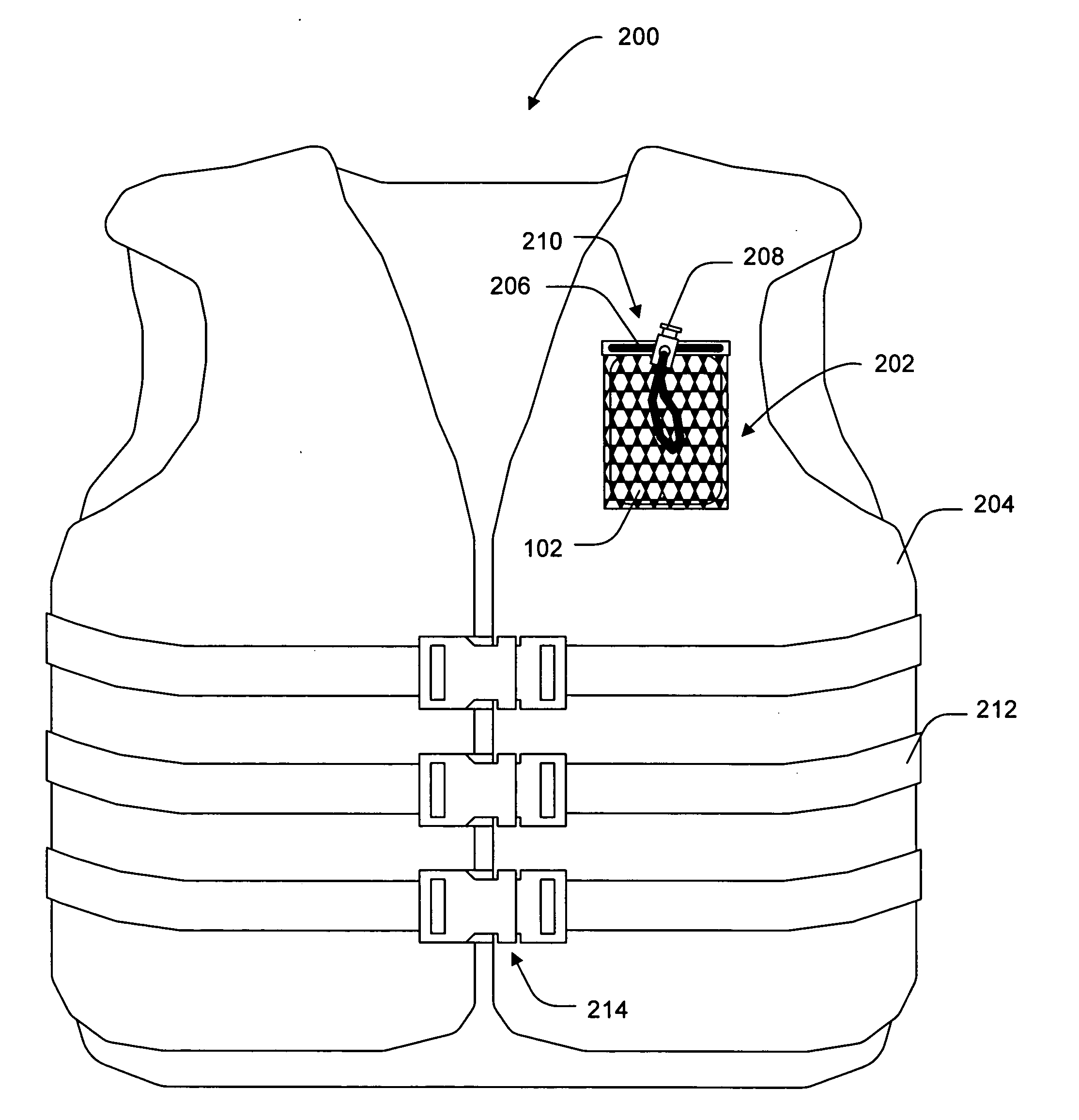
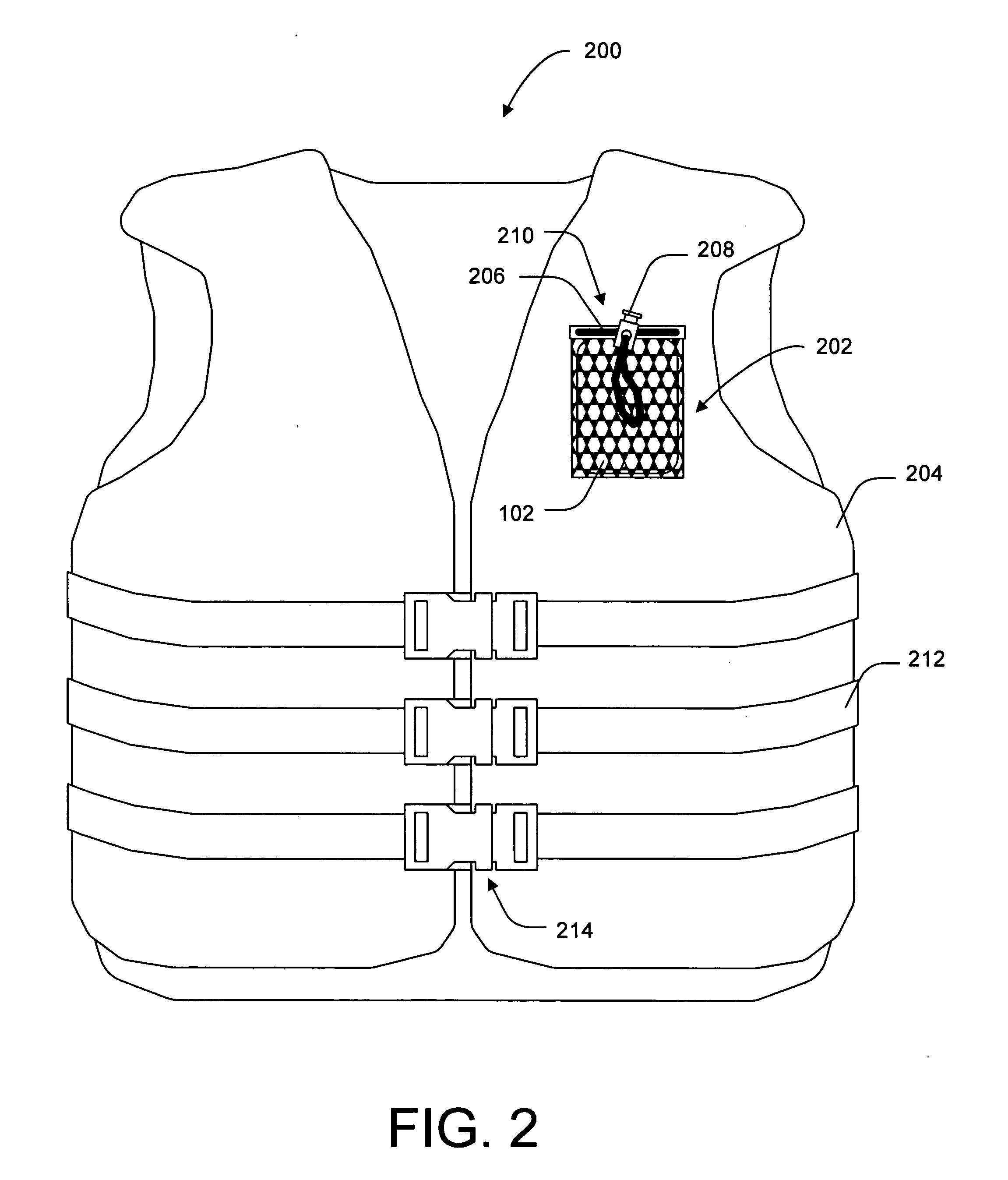
[0038]The present invention overcomes problems associated with the prior art, by providing a tracking device coupled to a buoyant component. The tracking device includes a wireless communication device configured to communicate via a terrestrial based network (e.g., a cell phone network). The tracking device can be conveniently attached to wearable PFDs and other buoyant components, because of the device's relatively small size as compared to a satellite telephone. In the following description, numerous specific details are set forth (e.g., particular electronic components, particular buoyant components, etc.) in order to provide a thorough understanding of the invention. Those skilled in the art will recognize, however, that the invention may be practiced apart from these specific details. In other instances, details of well known PFD manufacturing and electronics assembly practices and components have been omitted, so as not to unnecessarily obscure the present invention.

[0039]FIG...


PUM


Abstract

A personal safety device includes a buoyant component and a tracking device coupled to the buoyant component. The tracking device includes a location determining device and a wireless communication device. The wireless communication device is configured to communicate with a terrestrial communication network such as a cell phone network. The wireless communication device is effective in coastal and inland waters, and the reduced size as compared with satellite telephones makes the device practical use during recreational water activities. Various buoyant components including personal floatation devices, waterproof containers, and gas trapping encapsualtions are disclosed.

Description

BACKGROUND OF THE INVENTION[0001]1. Field of the Invention[0002]This invention relates generally to personal tracking devices, and more particularly to a personal tracking device having a buoyant component. Even more particularly, the invention relates to a personal tracking device in combination with a personal flotation device (PFD).[0003]2. Description of the Background Art[0004]Tracking devices embedded in personal flotation devices (PFDs) are known in the art. These devices are typically used in emergencies as a means to locate persons who are lost at sea, or have become separated from their vessel.[0005]A problem with some prior art tracking devices is that they require mechanical activation by the user. However, in an emergency situation, a user may not be able to activate the device due to injury, unfamiliarity with the operation of the device, or some other reason. To address this problem, devices with automatic trigger mechanisms have been developed.[0006]One such device i...

Claims


Application Information

Patent Timeline
Patent Type & Authority Applications(United States)
IPC IPC(8): G08B1/08G08B23/00
CPCB63C9/115B63C9/20G01S5/0205G01S5/0027B63C2009/0017B63C9/11B63C9/1255B63B2203/00B63B2213/02
Inventor BERTAGNA, PATRICK E.COHEN, JAMES H.
Owner GLOBAL TREK XPLORATION CORP
Why Eureka
Try Eureka