Beam combiner for projection system

Inactive Publication Date: 2007-10-18
DELTA ELECTRONICS INC
View PDF8 Cites 4 Cited by
  • Summary
  • Abstract
  • Description
  • Claims
  • Application Information

AI Technical Summary

Benefits of technology

[0012]Accordingly, excessive coating remaining after the coating of each prism with a high reflective coating. After

Problems solved by technology

Thus, signal light sources consumed more power are used.
Thus, t

Method used


Image

  • Beam combiner for projection system
  • Beam combiner for projection system
  • Beam combiner for projection system

Examples


Embodiment Construction

[0026]The following description is of the best-contemplated mode of carrying out the invention. This description is made for the purpose of illustrating the general principles of the invention and should not be taken in a limiting sense. The scope of the invention is best determined by reference to the appended claims.

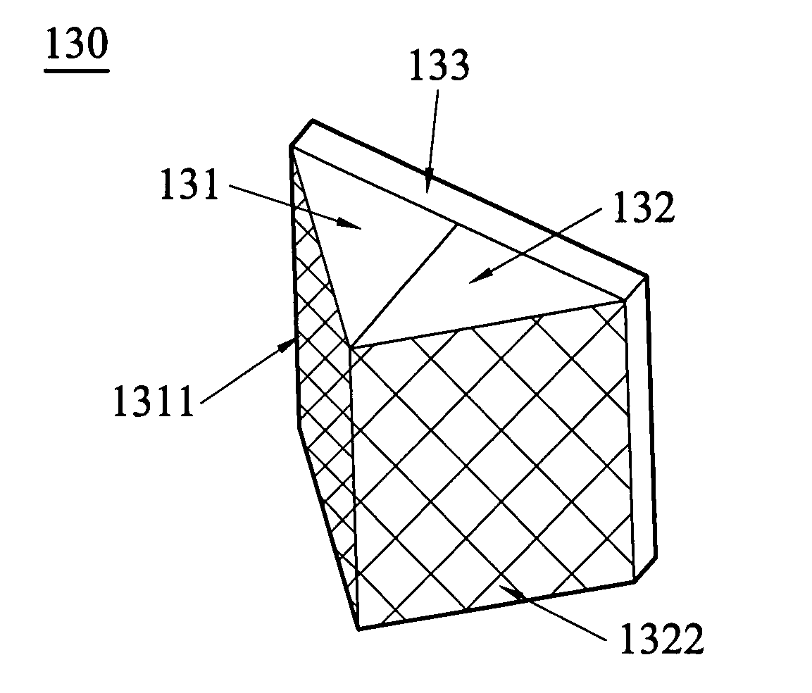
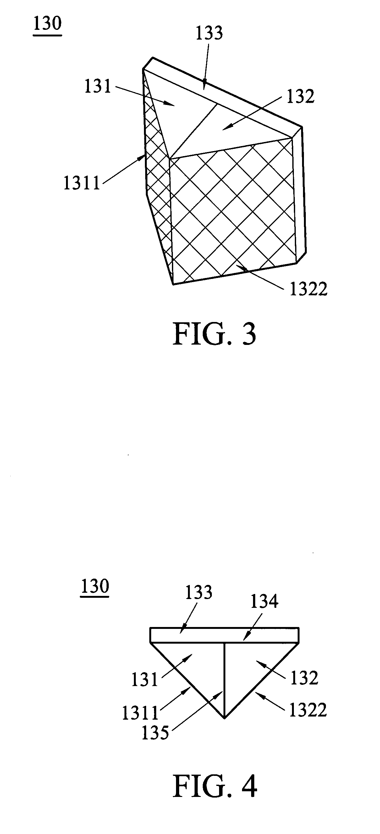
[0027]FIG. 3 is a schematic view which depicts a beam combiner 130 of an embodiment of the invention. The beam combiner 130 includes a prism 131 and a prism 132. In this embodiment, the prism is preferably a rectangular prism. The surfaces of each prism are polished to yield smooth surfaces. The prisms 131 and 132 respectively include a reflective surface 1311 and a reflective surface1322 coated with a high reflective coating. When the reflective surface of the prism 131 is coated, excessive coating accumulation on other planes has no effect. In this embodiment, the prisms 131 and 132 are attached to a plate 133. The material of the plate 133 is not limited to glass. O...


PUM


Abstract

A beam combiner and a projection system are disclosed. The projection system includes at least two light sources, a beam combiner, a light tunnel, a light modulator, and a screen. The beam combiner includes at least two prisms. Each prism includes a reflective surface and at least a combining surface. The reflective surface is coated with a high reflective coating and each prism is combined with another prism at the combining surface. The light modulator produces image signal. Light produced from the at least two light sources is reflected by the beam combiner, and enters the light tunnel and the light modulator sequentially, and the screen receives the image signal from the light modulator.

Description

CROSS-REFERENCE TO RELATED APPLICATIONS[0001]This application is related to U.S. Pat. No. 6,765,727 filed on Jun. 18, 2003, assigned to assignee of the present invention, and incorporated herein by reference.BACKGROUND OF THE INVENTION[0002]1. Field of the Invention[0003]The invention relates to a beam combiner, and in particular, to a beam combiner for a projection system.[0004]2. Description of the Related Art[0005]Present optical projection systems, such as projectors or projection televisions, project a single light beam to a light modulator. The light modulator arranges a light route for image signals in the projector system. For example, the digital micromirror device (DMD) is manufactured by Texas Instruments Inc. FIG. 1 is a schematic view of a conventional projector illumination system, wherein the light produced from a light source 12 is reflected by a reflective shell 24 and is gathered sequentially into a light tunnel 14 and the light modulator 10. The light passes throu...

Claims


Application Information

Patent Timeline
IPC IPC(8): G03B21/00
CPCG02B5/04G02B27/1073H04N9/315G03B21/14G02B27/143G03B21/208G03B33/12
Inventor CHEN, YU-CHUANYEN, SHAN-FENG
Owner DELTA ELECTRONICS INC
Why Eureka
Try Eureka