Diode-pumped solid-state laser device and manufacturing method of the same

a solid-state laser and pumping technology, which is applied in the direction of laser cooling arrangements, laser details, electrical devices, etc., can solve the problems of deterioration of laser beam profile quality, laser output saturation, and increased thermal lensing effect of laser rod, so as to reduce transmission loss, pump laser rod efficiently, and simple configuration

Inactive Publication Date: 2007-06-19
NEC CORP
View PDF13 Cites 2 Cited by
  • Summary
  • Abstract
  • Description
  • Claims
  • Application Information

AI Technical Summary

Benefits of technology

[0024]According to the present invention, the diode-pumped solid-state laser device of the present invention has a simple configuration including a pumping LD, a cooling tube, and a laser rod, and on the outer surface of the cooling tube are provided a antireflection coating to reduce a transmission loss in each ray of LD light and a high reflection coating to allow LD light having passed through the laser rod without being absorbed therein to be absorbed in the laser rod again, alternately in a stripe fashion and in the longitudinal direction of the laser rod, while the pumping LD pumps the laser rod with the optical axis thereof being positively tilted with respect to the center of the laser rod. It is thus possible to pump the laser rod efficiently, and as a consequence, a highly reliable, inexpensive laser with a high output and a high beam quality can be obtained.

Problems solved by technology

For example, when the distribution of pumping light within the laser rod makes a profile with the center of the rod being higher, the thermal lensing effect in the laser rod becomes greater, which raises problems, such as saturation of a laser output, deterioration in the quality of a laser beam profile, and damage in the laser rod.
However, because the LD light 13 heats the optical diffusing reflector 15, there arises a problem that heat damages the diffusing reflection mirror.
As has been described, the conventional method has a problem that costs are increased and the fabrication becomes complicated due to plural components, such as the optical diffusing reflector, the condenser lenses, a holding mechanism and a cooling mechanism of the optical diffusing reflector.
With the technique disclosed in the aforementioned publication, however, a patterned reflection coating has to be provided on the inner surface of the cylindrical member which is a difficult fabricating method.
Moreover, it is necessary to adjust in such a manner that pumping LD light that goes incident on the cylindrical member will be reflected on the reflection coating on the inner surface of the cylindrical member and returned to the incident position again (referred to as the condition for direct reflection in the aforementioned publication), which makes it quite difficult to align the pumping LDs.
For the reasons described above, the diode-pumped solid-state laser device manufactured with the use of the disclosed technique has a drawback that the costs are increased as a matter of course.

Method used


Image

  • Diode-pumped solid-state laser device and manufacturing method of the same
  • Diode-pumped solid-state laser device and manufacturing method of the same
  • Diode-pumped solid-state laser device and manufacturing method of the same

Examples


first embodiment

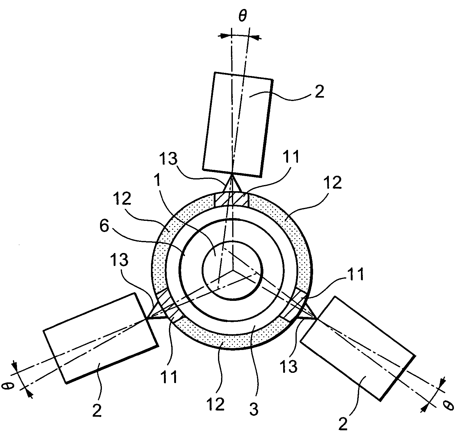
[0035]FIG. 3 is a diagram of the diode-pumped solid-state laser device of the present invention, showing a cross section normal to the axis of the laser rod 1. Herein, three pumping LDs 2 are placed at regular angular interval of 120° within the cross section of the laser rod 1. However, as many pumping LDs 2 as are structurally permissible, for example, 4 or 5 pumping LDs 2, may be placed. Alternatively, a number of pumping LDs 2 may be provided in a spiral fashion along the axis of the laser rod 1.

[0036]The outer surface of the cooling tube 3 is coated with an antireflection coating 11 and a high reflection coating 12, which are provided alternately along the circumferential direction and in a stripe fashion in the longitudinal direction of the laser rod 1. The antireflection coating 11 reduces a transmission loss in each ray of LD light 13. The high reflection coating 12 reflects LD light 13 that has passed through the laser rod 1 without being absorbed therein back to the laser ...

second embodiment

[0043]To be more specific, the antireflection coating 11 and the high reflection coating 12 may be provided as in the configuration of the diode-pumped solid-state laser device of the present invention shown in FIG. 4. That is, coating with the high reflection coating 12 is provided to the outer surface of the cooling tube 3 in a stripe fashion and in the longitudinal direction of the laser rod 1 first, and thence coating with the antireflection coating 11 is provided to cover the entire outer surface of the cooling tube 3 including the surface of the high reflection coating 12.

third embodiment

[0044]Further, the antireflection coating 11 and the high reflection coating 12 may be provided as in the configuration of the diode-pumped solid-state laser device of the present invention shown in FIG. 5. That is, coating with the antireflection coating 11 is provided across the entire outer surface of the cooling tube 3 first, and thence coating with the high reflection coating 12 is provided on the outer surface of the antireflection coating 11 in a stripe fashion and in the longitudinal direction of the laser rod 1.

[0045]By adopting the configuration in any of the first through third embodiments above, the LD light irradiated from each pumping LD passes through the antireflection coating on the cooling tube with a little loss, and is thereby absorbed into the laser rod efficiently. The LD light that has passed through the laser rod without being absorbed therein is reflected on the high reflection coating provided on the surface opposite to the cooling tube and is returned to t...


PUM


Abstract

A conventional method for a solid-state laser device that obtains a laser beam output of a high quality at a high output using a laser diode as a pumping light source has a problem that the costs are increased and the fabrication becomes complicated due to an increasing number of components, such as a diffusing reflection mirror, a condenser lens, and a holding mechanism and a cooling mechanism thereof. Coating with a antireflection coating to reduce a transmission loss of laser diode light, and coating with a high reflection coating to reflect the laser diode light are provided alternately on the outer surface of a cooling tube. Also, an irradiation direction of the laser diode is not directed to the center of the laser rod, but is given with a certain angle to be positively tilted. This configuration makes it possible to eliminate the above problem.

Description

BACKGROUND OF THE INVENTION[0001]1. Field of the Invention[0002]The present invention relates to a diode-pumped solid-state laser device and a manufacturing method of the same.[0003]2. Description of the Related Prior Art[0004]For a diode-pumped solid-state laser device to obtain a laser beam of a high beam quality at a high output, it is necessary to achieve a homogeneous distribution of pumping light within a laser rod across the cross section of the rod. For example, when the distribution of pumping light within the laser rod makes a profile with the center of the rod being higher, the thermal lensing effect in the laser rod becomes greater, which raises problems, such as saturation of a laser output, deterioration in the quality of a laser beam profile, and damage in the laser rod. Conventionally, the optical diffusing and condensing method has been proposed in order to achieve a homogenous pumping distribution within the laser rod.[0005]FIG. 1 shows a cross section of a convent...

Claims


Application Information

Patent Timeline
Patent Type & Authority Patents(United States)
IPC IPC(8): H01S3/093H01S3/094H01S3/04H01S3/042H01S3/0941
CPCH01S3/0941H01S3/025H01S3/0407H01S3/042H01S3/094084
Inventor MUKAIHARA, KATSUJITSUNEKANE, MASAKI
Owner NEC CORP
Why Eureka
Try Eureka