Reflective optical element for EUV lithography

a technology of optical elements and lithography, applied in the field of reflection optical elements, can solve the problems of increasing the micro roughness of the surface of each layer, the optical element is substantially interfered, and the expensive special coating method cannot be resorted to, so as to achieve good stress compensation, simplify the entire coating method, and good stress compensation

Active Publication Date: 2012-01-19
CARL ZEISS SMT GMBH
View PDF5 Cites 13 Cited by
  • Summary
  • Abstract
  • Description
  • Claims
  • Application Information

AI Technical Summary

Benefits of technology

[0015]It has been found that nickel and nickel alloys are particularly suitable to compensate layer stresses generated by reflective multilayer systems, which are optimized for wavelengths in the EUV range. Among others, nickel-silicon, nickel-boron, nickel-molybdenum, nickel-silicon-boron or nickel-vanadium, for example, are preferred. In preferred embodiments, the second multilayer system consists of periods of layers of nickel or a nickel alloy and at least two layers of the materials having different real parts of the refractive index at the working wavelength of the first multilayer system. The use of materials of the first multilayer system also in the second multilayer system enables the entire coating method to be simplified.
[0016]In further preferred embodiments, the second multilayer system consists of periods of two alternatingly arranged layers of two materials, one of which is nickel or a nickel alloy, and a layer of a third material, to achieve good stress compensation.
[0017]It has also been found advantageous for good stress compensation to build up the second multilayer system of periods of first layers of nickel or nickel alloys and second layers of a further metal.

Problems solved by technology

As early as during the coating process, a stress can build up within a multilayer system, which has an effect on the underlying substrate and deforms it to an extent that the optical imaging on the corresponding reflective optical element is substantially interfered with.
This can lead to increased micro roughness of the surface of each layer, which can also continue into the layers on top of it.
In particular, expensive special coating methods need not be resorted to, which work with highly energetic layer-forming particles of 40 eV and way above that, such as laser-pulsed coating methods.

Method used


Image

  • Reflective optical element for EUV lithography
  • Reflective optical element for EUV lithography
  • Reflective optical element for EUV lithography

Examples


Embodiment Construction

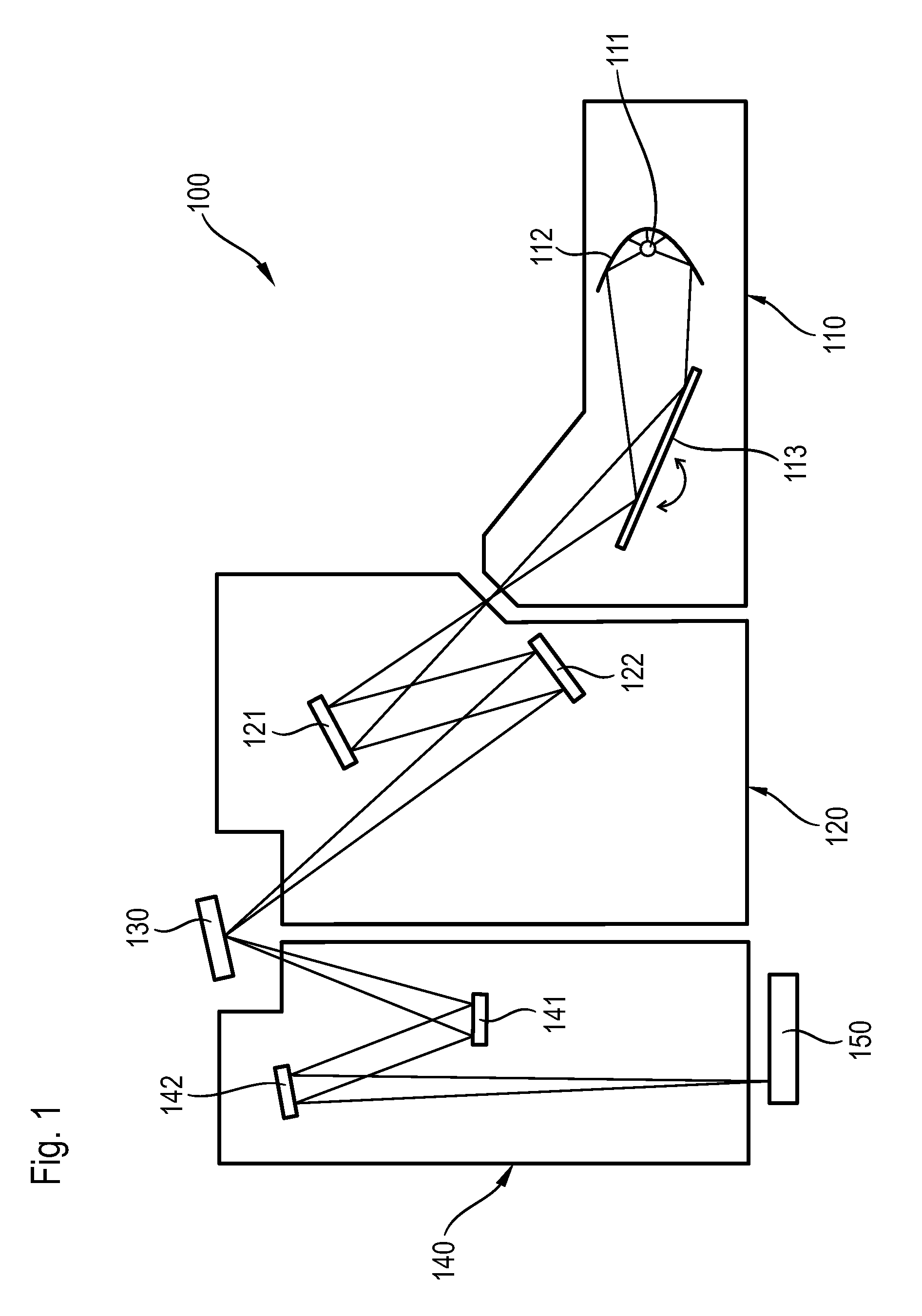
[0034]FIG. 1 schematically shows an EUV lithography apparatus 100. Substantial components thereof are the beam-shaping system 110, the illumination system 120, the photomask 130, and the projection system 140.

[0035]A plasma source or even a synchrotron can serve, for example, as a radiation source 111. For the wavelength range from 5 nm to 12 nm, in particular, X-ray lasers (X-FEL) are also suitable as a radiation source. The radiation emitted is first focused by a collector mirror 112. Moreover, a monochromator 113 is used to filter out the operating wavelength by varying the angle of incidence. In the wavelength range mentioned, the collector mirror 112 and the monochromator 113 are usually formed as reflective optical elements having a multilayer system of at least two alternating materials with different real parts of the refractive index at the working wavelength in order to achieve reflection of the radiation of the working wavelength. Collector mirrors are usually dish-like r...


PUM


Abstract

A stress-reduced reflective optical element for a working wavelength in the soft X-ray and extreme ultraviolet wavelength range includes a first multilayer system (4) of at least two alternating materials (41, 42) having different real parts of the refractive index at the working wavelength on a substrate (2), which exerts a layer stress on the substrate (2), and comprising a second multilayer system (6) of at least two alternating materials (61, 62) on a substrate (2), which exerts an opposed layer stress on the substrate (2) and is arranged between the first multilayer system (4) and the substrate (2), wherein one of the materials (61) of the second multilayer system (6) is nickel-vanadium-silicon, and wherein the ratio (G) of the overall thickness of nickel-vanadium-silicon layers (61) within one period (60) of the second multilayer system (6) to the overall thickness of the period (60) of the second multilayer system (6) is at least 0.25.

Description

CROSS-REFERENCE TO RELATED PATENT APPLICATIONS[0001]This is a Continuation-in-part of International Application PCT / EP2010 / 069553, with an international filing date of Dec. 13, 2010, which was published under PCT Article 21(2) in English, which claims priority under 35 U.S.C. §119(a) to German Patent Application No. 10 2009 054 653.7, filed on Dec. 15, 2009, the entire contents of which are hereby incorporated by reference.FIELD AND BACKGROUND[0002]The present invention relates to reflective optical elements for a working wavelength in the soft X-ray and extreme ultraviolet wavelength ranges, in particular for use in an EUV lithography apparatus comprising a first multilayer system of at least two alternating materials having different real parts of the refractive index at the working wavelength on a substrate, which exerts a layer stress on the substrate, and comprising a second multilayer system of at least two materials, periodically alternating, as the case may be, on a substrat...

Claims


Application Information

Patent Timeline
Patent Type & Authority Applications(United States)
IPC IPC(8): G02B5/08
CPCG02B1/105G02B5/0816G02B5/0891B82Y30/00G03F7/70316G03F7/70958G03F7/70233G02B1/10G02B1/14
Inventor WEBER, JOERN
Owner CARL ZEISS SMT GMBH
Why Eureka
Try Eureka