Laser

Inactive Publication Date: 2020-01-30
HUAWEI TECH CO LTD
View PDF0 Cites 0 Cited by
  • Summary
  • Abstract
  • Description
  • Claims
  • Application Information

AI Technical Summary

Benefits of technology

The patent describes a new design for a laser that has improved performance and stability. It includes a rear reflector with a high reflection coating, which increases the laser's performance. The laser's output ratio is stable and low, making it more insensitive to external optical reflection. The length of the Bragg grating and the grating strength are optimized to achieve better performance. The laser operates in Fabry-Perot mode, which allows it to function at multiple longitudinal modes simultaneously. The front face is coated with an anti-reflection coating to improve performance.

Problems solved by technology

Cleaving is a mechanical operation, and it is difficult to control with the utmost precision.
During the manufacture of a laser, it is very difficult to control precisely where the material cleaves to form a facet.
Standard DFB lasers suffer yield loss as a result of the random phase of the waves reflected from the facets.
However, if the reflection is from a coupling lens, for example connecting the laser to an optical fibre, it is very difficult to solve this problem.
Additionally, the optical isolators usually inserted in DFB laser modules to reduce the optical reflection make the laser modules more expensive and larger than desired.

Method used


Image

  • Laser

Examples


Embodiment Construction

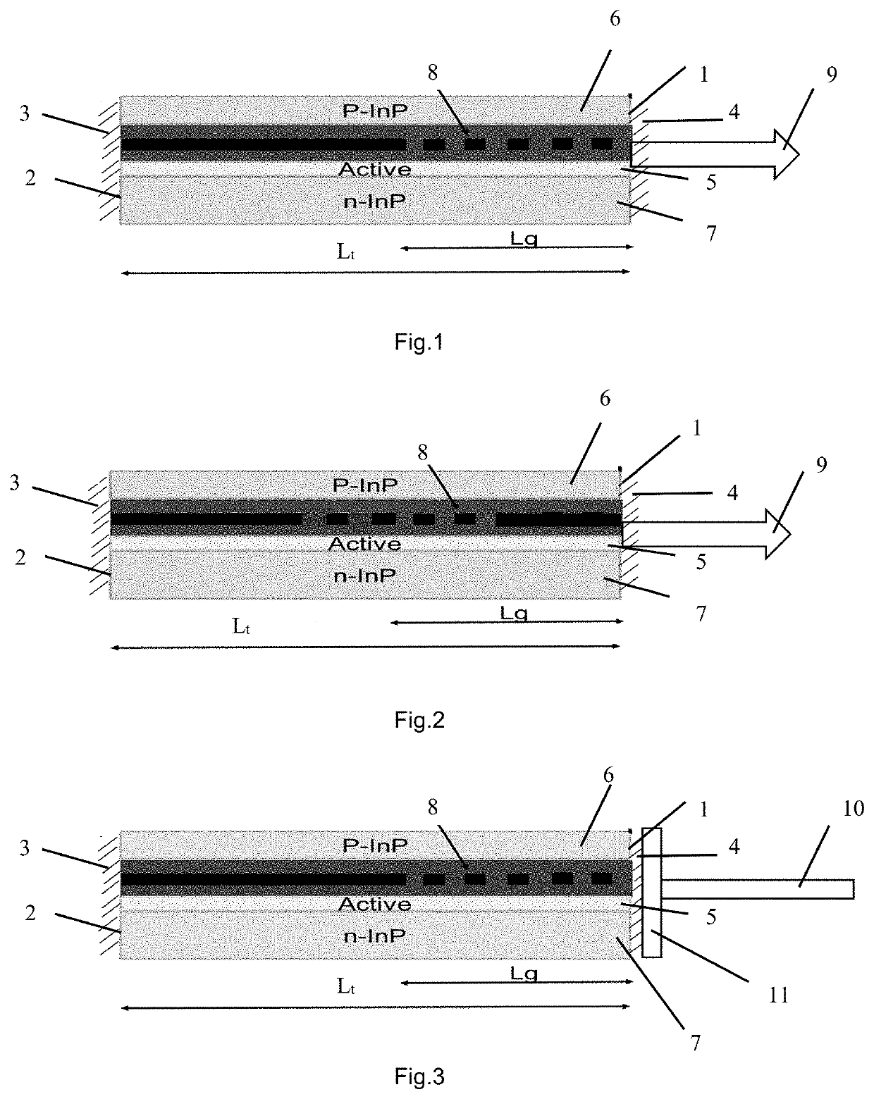
[0033]As illustrated in FIG. 1, one form of laser comprises a semiconductor block which has a front face or facet 1, a rear face or facet 2 opposite to the front face or facet and a laser cavity formed therebetween. The total length of the laser cavity is Lt. A high reflection (HR) coating 3 is applied to the rear facet and an anti-reflection (AR) coating 4 is applied to the front facet. The back facet with the HR coating acts as a rear reflector.

[0034]In the example shown in FIG. 1, the laser cavity comprises an active layer 5 interposed between layers of p- and n-type semiconductor material, shown at 6 and 7 respectively. A Bragg grating 8 is positioned adjacent to the front facet between the active layer 5 and the p-type semiconductor layer 6. The grating may alternatively be positioned between the active layer and the n-type semiconductor layer 7. The Bragg grating is integral with the cavity of the laser. The Bragg grating has a length Lg. The Bragg grating is elongated along t...


PUM


Abstract

An example laser has a rear reflector, a front facet spaced from the rear reflector, and a laser cavity defined between the rear reflector and the front facet. The laser comprises a Bragg grating located in the laser cavity, where a length of the Bragg grating (Lg) is in a range from 40% to 60% of a distance from the rear reflector to front of the Bragg grating, and a grating strength (Kappa*Lg) is in a range from 0.6 to 1.5.

Description

CROSS-REFERENCE TO RELATED APPLICATIONS[0001]This application is a continuation of International Application No. PCT / EP2017 / 058416, filed on Apr. 7, 2017, the disclosure of which is hereby incorporated by reference in its entirety.BACKGROUND[0002]This invention relates to lasers, for example to improving the yield and reflection tolerance of distributed feedback lasers.[0003]High-performance and low-cost laser modules are used in applications such as large-capacity and high-speed optical access networks.[0004]A conventional laser diode generally comprises a semiconductor block which has a front face or facet, a rear face or facet opposite to the front facet and a laser cavity formed therebetween. The cavity traditionally comprises an active layer interposed between layers of p- or n-type semiconductor material. One or more coating layer(s), such as anti-reflection (AR) or high reflection (HR) coatings, may be applied to the front and the rear facets to provide a predetermined reflec...

Claims


Application Information

Patent Timeline
IPC IPC(8): H01S5/12H01S5/10H01S5/065H01S5/028H01S5/022H01S5/30
CPCH01S5/02284H01S5/0653H01S5/1203H01S5/3013H01S5/0287H01S5/02288H01S5/1039H01S5/02251H01S5/02253
Inventor CHEN, XIN
Owner HUAWEI TECH CO LTD
Why Eureka
Try Eureka