
Semiconductor memory device

a memory device and semiconductor technology, applied in the field of semiconductor memory devices, can solve the problems of data not being held within the refresh test time, memory cells becoming defective, and disturb refresh test time occupying a large proportion of memory test time, so as to reduce the disturb refresh test time

Inactive Publication Date: 2007-10-18
PANASONIC SEMICON SOLUTIONS CO LTD
View PDF9 Cites 1 Cited by
  • Summary
  • Abstract
  • Description
  • Claims
  • Application Information

AI Technical Summary

Benefits of technology

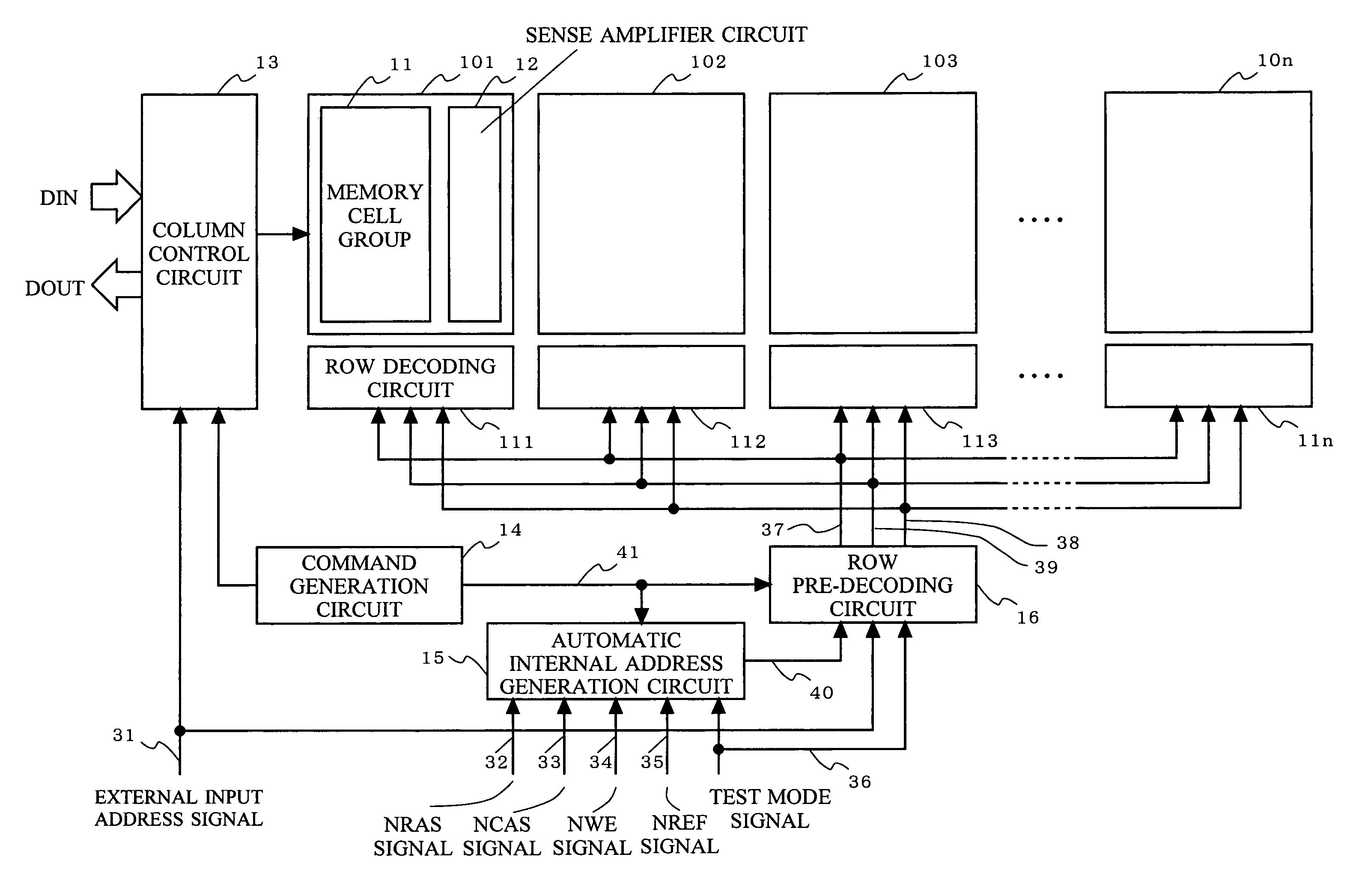
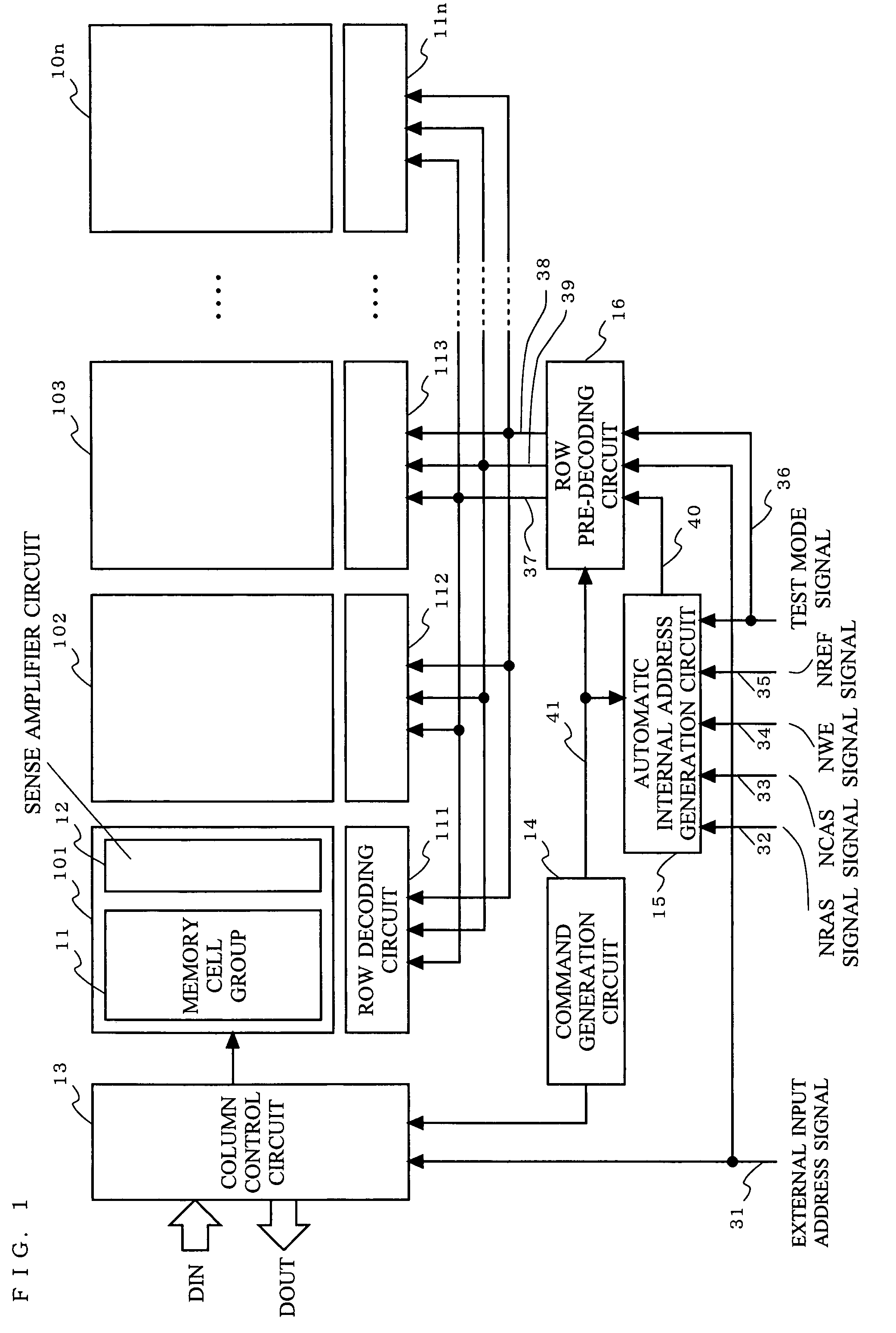
The present invention is a semiconductor memory device that reduces the time required for refreshing data without increasing the size of the control circuitry and causing delays in the decoding of row signals. The device includes a plurality of memory cell arrays, each containing a memory cell group and a sense amplifier circuit. The device selects two or more memory cell arrays for automatic data refresh based on external commands, refreshing data in the memory cell groups connected to the selected word lines. The device also disconnects the sense amplifier circuit and data lines during the refresh operation to avoid interference. The invention achieves a reduction in the time required for the disturb refresh test by switching the address signals for selecting word lines from internally generated signals to externally inputted signals. In a test mode, the invention activates the same number of memory cell arrays as the number of activation control signals generated during the automatic data refresh operation for the memory cell group, reducing the disturb test time.

Problems solved by technology

Here, in a case of memory cells whose transistor threshold voltages are low, since large subthreshold currents flow, data cannot be held within refresh test time and the memory cells become defective.
Therefore, the disturb refresh test time occupies a large proportion of memory test time.
Therefore, the conventional methods not only increase an area of a control circuitry section but also delay a row decoding signal, leading to a problem of impeding a high-speed operation of a memory.

Method used


Image

  • Semiconductor memory device
  • Semiconductor memory device
  • Semiconductor memory device

Examples


first embodiment

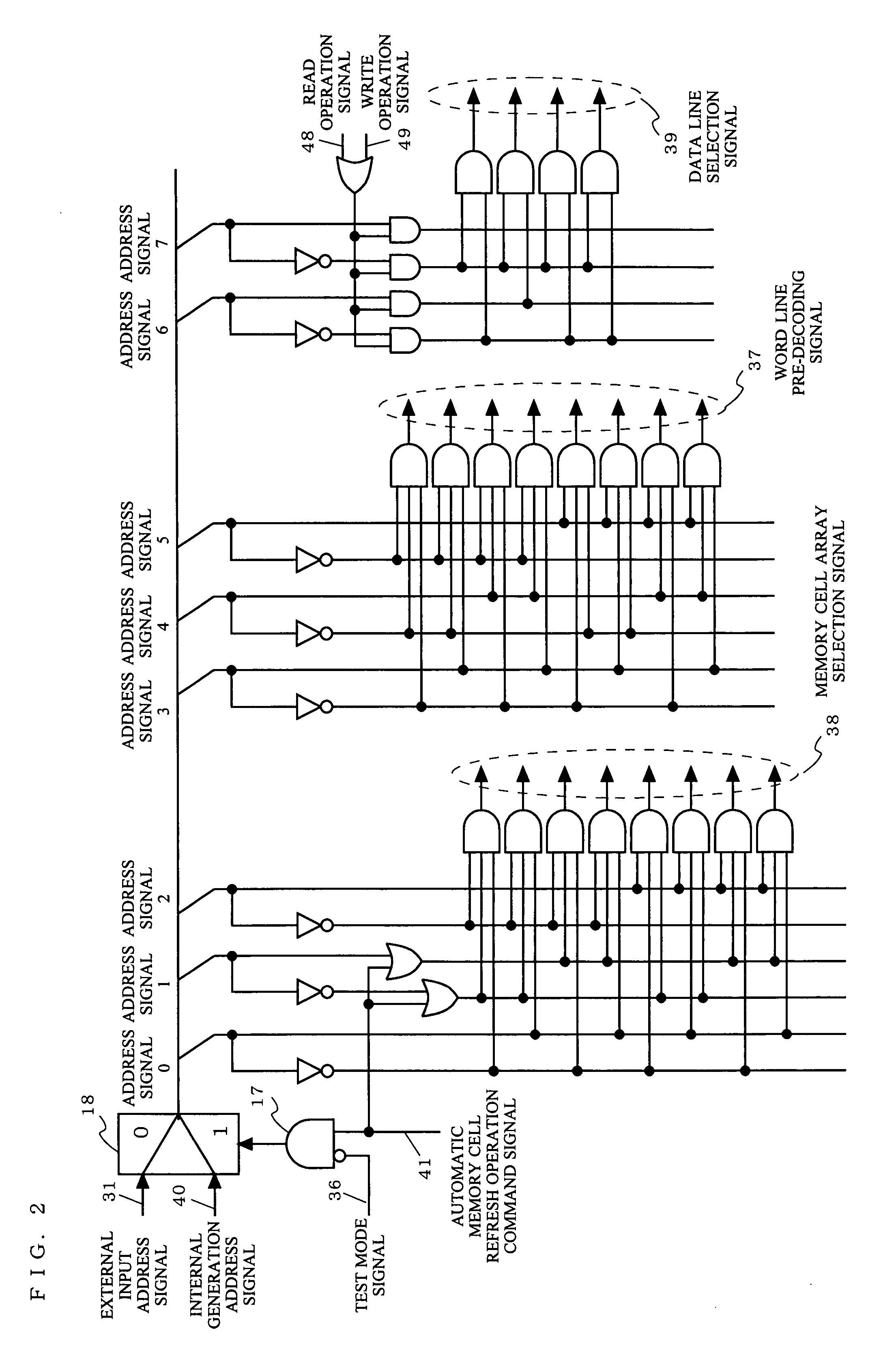
[0026]FIG. 2 is a diagram illustrating an exemplary configuration of a row pre-decoding circuit 16 according to a first embodiment of the present invention. The row pre-decoding circuit 16 according to the first embodiment is different from the conventional row pre-decoding circuit 56 in that the row pre-decoding circuit 16 includes a logic element 17 in which a test mode signal 36 is inputted and a logical product of an inversion signal of the test mode signal 36 and the automatic memory cell refresh operation command signal 41 is found.

[0027]When the row pre-decoding circuit 16 according to the first embodiment operates in a normal mode, the test mode signal 36 is set at a low level. In the state of this normal mode, when the automatic memory cell refresh operation command signal 41 reaches a high level, the internally generated address signal 40 is selected in a selector 18. And when the automatic memory cell refresh operation command signal 41 reaches a high level, an address si...

second embodiment

[0037]FIG. 3 is a diagram illustrating an exemplary configuration of a row pre-decoding circuit 16 according to a second embodiment of the present invention. The row pre-decoding circuit 16 according to the second embodiment is different from the conventional row pre-decoding circuit 56 in that the row pre-decoding circuit 16 includes: a logic element 19 in which a test mode signal 36 is inputted and a logical product of a test mode signal 36 and a read operation signal 48 is found; and a logic element 20 in which a logical sum of an output of the logic element 19 and an automatic memory cell refresh operation command signal 41 is found.

[0038]When the row pre-decoding circuit 16 according to the second embodiment operates in a normal mode, the test mode signal 36 is set at a low level. In a state of this normal mode, a read operation, a write operation, and an automatic memory cell refresh operation are same as those in the above-described first embodiment.

[0039]Next, a case of a te...

third embodiment

[0049]FIG. 4 is a diagram illustrating an exemplary configuration of a row pre-decoding circuit 16 according to a third embodiment according to the present invention. The row pre-decoding circuit 16 according to the third embodiment is different from the conventional row pre-decoding circuit 56 in that the row pre-decoding circuit 16 includes a logic element 21 in which a test mode signal 36 is inputted and a logical sum of the test mode signal 36 and an automatic memory cell refresh operation command signal 41 is found.

[0050]The row pre-decoding circuit 16 in the third embodiment supports an RAS refresh operation for any memory cells by using an externally inputted address signal 31 as an externally inputted command. When the row pre-decoding circuit 16 in the third embodiment is set to be in a test mode state, the row pre-decoding circuit 16 is characterized in that memory cell arrays, the number of which is equal to that of the memory cell arrays which are activated in an automat...


PUM


Abstract

Through setting an internal test mode, a refresh operation for a DRAM is carried out by externally inputted address signals, instead of internally generated address signals, while maintaining the same number of memory cell arrays to be activated as that of memory cell arrays which are concurrently activated in a refresh for memory cell arrays. This configuration needs no drastic addition of circuits and allows a reduction in disturb test time for a plurality of memory cell arrays.

Description

BACKGROUND OF THE INVENTION[0001]1. Field of the Invention[0002]The present invention relates to a semiconductor memory device and more particularly, to a semiconductor memory device, such as a dynamic random access memory (DRAM), which includes a test circuit for detecting leakage failure in memory cell transistors.[0003]2. Description of the Background Art[0004]As a test method (hereinafter, referred to as “a disturb refresh test”) for detecting leakage failure in memory cell transistors in a conventional semiconductor memory device, or in particular, in DRAM, there is, for example, the following method.[0005]First, high (or low) data is written into all memory cells (write operation). After writing the data into all the memory cells, any word lines are activated and charges in the memory cells are read out to bit lines intersecting the activated word lines. And by amplifying the read-out charges in a sense amplifier circuit (read / refresh operation), potentials in the bit lines an...

Claims


Application Information

Patent Timeline
Patent Type & Authority Applications(United States)
IPC IPC(8): G11C7/00
CPCG11C11/401G11C2029/2602G11C29/26G11C11/406
Inventor SADAKATA, HIROYUKI
Owner PANASONIC SEMICON SOLUTIONS CO LTD
Learn More