Interface between a synchronous network and high-speed ethernet

Inactive Publication Date: 2007-10-18
CORRIGENT SYST LTD
View PDF42 Cites 39 Cited by
  • Summary
  • Abstract
  • Description
  • Claims
  • Application Information

AI Technical Summary

Benefits of technology

[0022] Typically, the synchronous optical network link includes at least one of a SONET OC-192 link and a SDH STM-64 link, and transmitting the flo

Problems solved by technology

This discrepancy can be problematic when the stream of frames is transported over the synchronous optical network at high

Method used


Image

  • Interface between a synchronous network and high-speed ethernet
  • Interface between a synchronous network and high-speed ethernet
  • Interface between a synchronous network and high-speed ethernet

Examples


Embodiment Construction

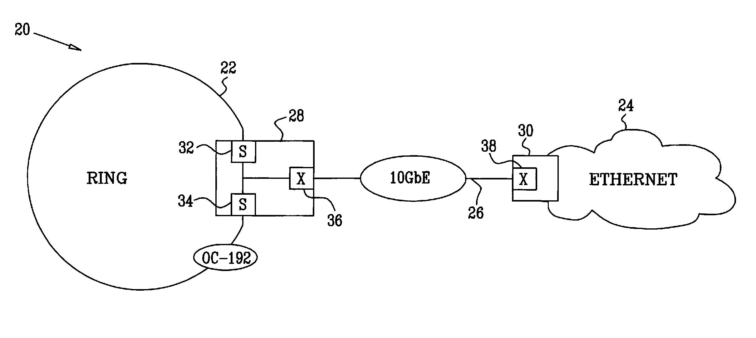
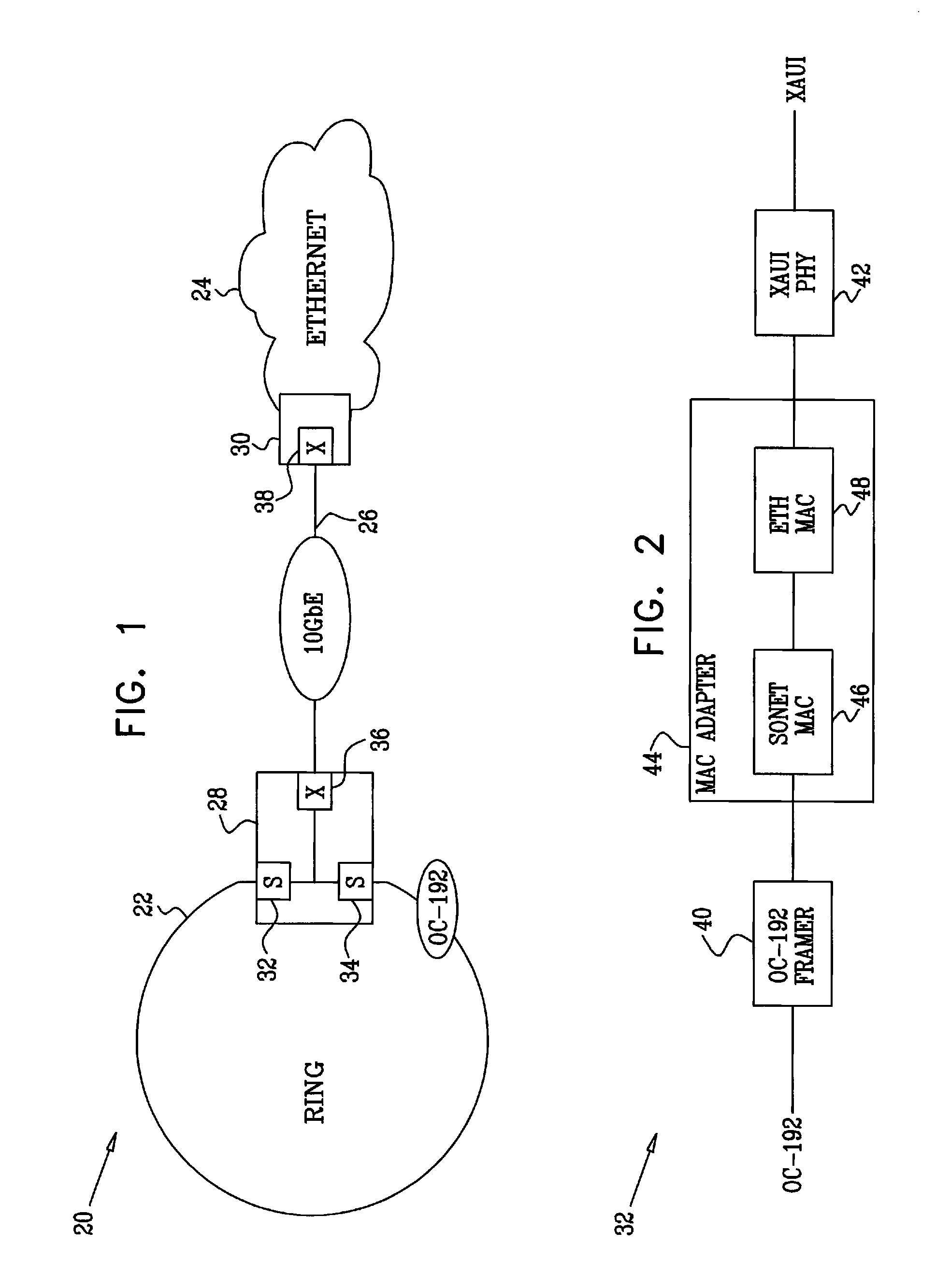
[0043]FIG. 1 is a block diagram that schematically illustrates a communication network system 20, in accordance with an embodiment of the present invention. System 20 in this example comprises a ring network 22 and a packet network 24. The ring network operates as a synchronous optical network in accordance with the SONET or SDH standard at the OC-192 (STM-64) line rate. The packet network is an Ethernet network. Networks 22 and 24 are connected by a 10 Gb / s Ethernet (10 GbE) link 26 between nodes 28 and 30.

[0044] Node 28 comprises “east” and “west” synchronous optical network interfaces 32 and 34, which connect to ring network 22 in accordance with the applicable synchronous optical network standard. (The terms “east” and “west” are used here solely for the sake of convenience and have no geographical meaning.) In an exemplary embodiment, network 22 is a bi-directional network, such as a Resilient Packet Ring (RPR) network, but the principles of this embodiment are applicable in c...


PUM


Abstract

A method for communication includes receiving over a synchronous optical network link a flow of encapsulated Ethernet data frames. Two or more of the Ethernet data frames are concatenated to form an extended frame having a single start frame delimiter (SFD) and a single end frame delimiter (EFD) in compliance with an Ethernet standard, and the extended frame is transmitted over an Ethernet link.

Description

FIELD OF THE INVENTION [0001] The present invention relates generally to data communications, and specifically to methods and systems for transferring packet communication traffic between TDM and packet networks. BACKGROUND OF THE INVENTION Definitions [0002] In the context of the present patent application and in the claims, the terms listed below shall be interpreted as follows: [0003] A synchronous optical network is a network operating in accordance with either SONET (Synchronous Optical Network) or SDH (Synchronous Digital Hierarchy) standards. These standards define a hierarchical set of transmission rates and transmission formats for carrying high-speed, time-domain-multiplexed (TDM) digital signals. [0004] An Ethernet network is a packet network operating in accordance with the IEEE 802.3 set of standards, which define a protocol and frame format for data communication. The terms “packet” and “frame” are used herein interchangeably. [0005] 10 Gigabit Ethernet (10 GbE) is a t...

Claims


Application Information

Patent Timeline
IPC IPC(8): H04L12/56
CPCH04J3/1617H04J2203/0085H04L49/9078H04L49/90H04L49/901H04J2203/0096
Inventor FRIDMAN, AMIT
Owner CORRIGENT SYST LTD
Why Eureka
Try Eureka