Method and apparatus to transmit data on PLC network by aggregating data

a technology of aggregating data and transmission methods, applied in the direction of signal transmission/receiving via power distribution, transmission of single/parallel channels of television signals, securing communication, etc., can solve the problems of increasing complexity of implementation, frequent overhead, and inability to implement itself, so as to achieve efficient request and execution, increase throughput, and improve efficiency

Active Publication Date: 2007-10-18
SAMSUNG ELECTRONICS CO LTD
View PDF11 Cites 16 Cited by
  • Summary
  • Abstract
  • Description
  • Claims
  • Application Information

AI Technical Summary

Benefits of technology

[0018]The present general inventive concept provides a data transmission method and apparatus by which when a variety of types and sizes of data units are transmitted in a high-speed power line communication (PLC) network, the data units are transmitted more efficiently, and when an error occurs in the transmission of the data, retransmission is efficiently requested and executed such that throughput can increase and quality of service (QoS) can be enhanced.

Problems solved by technology

When the data units of the variety of types and sizes are transferred to the MAC layer, if the data units are transmitted individually, frequent overheads can occur.
That is, if each of the data units transferred to the MAC layer from an upper layer or the PHY layer is transmitted individually in an individual frame, an ACK is individually generated in the frame corresponding to the data unit, thus causing an overhead.
In addition, header information, padding information, and cyclic redundancy check (CRC) information for each layer in the frame corresponding to each data unit are generated, and these may also cause overheads.
First, when a variety of types and sizes of data units are transferred to a MAC layer, they cannot be efficiently aggregated and transmitted. That is, when the data units have a variety of sizes, one whole data unit may be included in one frame block, but two or more frame blocks may be needed for one data unit. That is, since a data unit is not the same size as a frame block, it is difficult for an idealistic case where one data unit corresponds to one frame block, to occur. Accordingly, after a data unit is inserted into a frame block, a remaining empty part exists in the frame block. In this empty part, another data unit may be inserted or it may be left empty. Accordingly, when a variety of types and sizes of data units are aggregated and transmitted at a time according to the conventional technology, complexity of implementation increases or implementation itself may become impossible.
Secondly, when a variety of types and sizes of data units are aggregated and transmitted at the same time according to the conventional technology, the boundary and size of each data unit included in the frame block, the number of data units included in the frame block, the number of each data unit included in the frame block, and other information as well as basic information, such as the number of the frame block and cyclic redundancy check (CRC) information should be included in the delimiter containing information on a frame block. Accordingly, the quantity of information that should be included in the delimiter increases substantially.
Thirdly, as the types of upper layers to which a data unit is to be transferred increase in order to increase types and sizes of data units, the processing in a MAC layer becomes more complicated.
Accordingly, the conventional method causes many problems when a variety of types and sizes of data units to be transferred from a variety of upper layers are to be effectively aggregated and transmitted.

Method used


Image

  • Method and apparatus to transmit data on PLC network by aggregating data
  • Method and apparatus to transmit data on PLC network by aggregating data
  • Method and apparatus to transmit data on PLC network by aggregating data

Examples


Embodiment Construction

[0051]Reference will now be made in detail to the embodiments of the present general inventive concept, examples of which are illustrated in the accompanying drawings, wherein like reference numerals refer to the like elements throughout. The embodiments are described below in order to explain the present general inventive concept by referring to the figures.

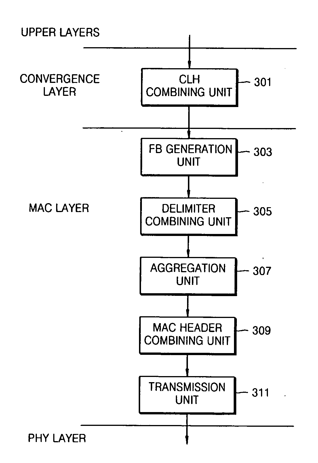
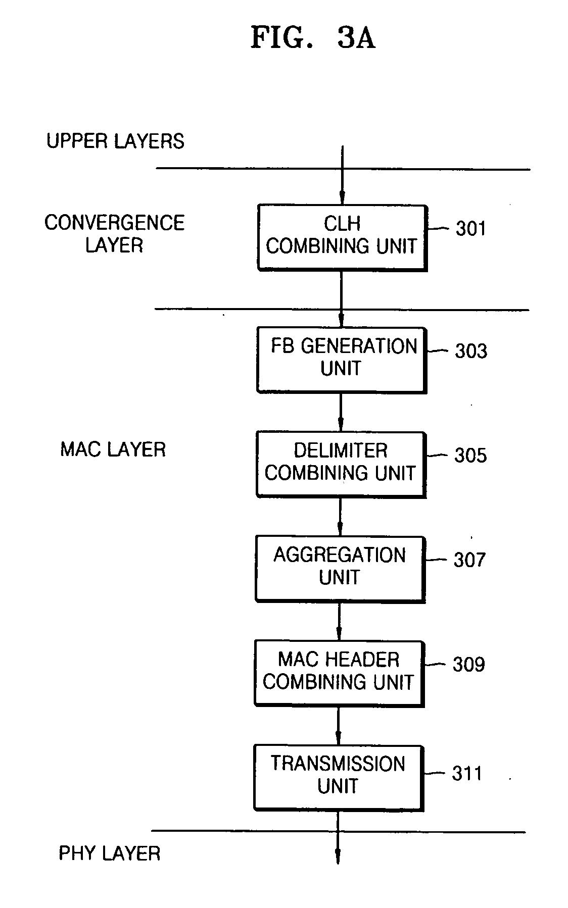
[0052]FIG. 3A is a diagram illustrating an apparatus to transmit data from upper layers to a PHY layer in a power line communication (PLC) network according to an embodiment of the present general inventive concept. FIGS. 6A through 6D are diagrams illustrating a method of processing data in the apparatus illustrated in FIG. 3A according to an embodiment of the present general inventive concept. The apparatus of FIG. 3A may be a PLC network device to communicate with another apparatus to transmit and / or receive data therebetween. The another apparatus may be another PLC network device or a device disposed outside the PLC network...


PUM


Abstract

A method and apparatus to efficiently transmit data. The method and apparatus effectively aggregate data and transmit the data in a high-speed power line communication (PLC) network. The method of transmitting the data includes combining each of at least one or more data units transferred from an upper layer, with a field to indicate attribute information of the data unit, dividing the combined data units and fields into frame blocks of an identical size, and aggregating the divided frame blocks and transferring the aggregated frame blocks as one frame to a PHY layer. In this way, data units of a variety of types and sizes transferred from the upper layer are aggregated and transmitted as the one frame.

Description

CROSS-REFERENCE TO RELATED APPLICATIONS[0001]This application claims priority under 35 U.S.C. §119(a) from Korean Patent Application No. 10-2006-0020639, filed on Mar. 3, 2006, in the Korean Intellectual Property Office, the disclosure of which is incorporated herein in its entirety by reference.BACKGROUND OF THE INVENTION[0002]1. Field of the Invention[0003]The present general inventive concept relates to a method and apparatus to efficiently transmit data and more particularly, to a method and apparatus to effectively aggregate data and transmit the data in a high-speed power line communication (PLC) network.[0004]2. Description of the Related Art[0005]When data is transmitted through a PLC network, data flows through a plurality of layers. FIG. 1 is a schematic diagram of a path along which data is transmitted through a plurality of layers in a PLC network.[0006]Data transmitted by a transmitter connected to the PLC network arrives at an upper layer through a PHY layer (physical ...

Claims


Application Information

Patent Timeline
Patent Type & Authority Applications(United States)
IPC IPC(8): H04B1/66
CPCH04B3/54H04L69/22H04B2203/5408H04L12/28H04L65/00H04L9/40
Inventor CHOI, JUN-HAECHANG, SEUNG-GIKWON, CHANG-YEULLEE, JOON-HEELEE, JUN-HAN
Owner SAMSUNG ELECTRONICS CO LTD
Why Eureka
Try Eureka