Spacer grid spring for increasing the conformal contact area with fuel rod

Active Publication Date: 2007-10-18
KOREA ATOMIC ENERGY RES INST +1
View PDF3 Cites 30 Cited by
  • Summary
  • Abstract
  • Description
  • Claims
  • Application Information

AI Technical Summary

Benefits of technology

[0025] Accordingly, the present invention has been made keeping in mind the above problems occurring in the prior art, and an object of the present invention is to provide spacer grid spring that increases the conformal contact area with a fuel rod, in which the spacer grid spring of the grid strap, which is in contact with the fuel rod, is optimized in shape, thereby the elasticity of the spacer grid spring contacting the fuel rod is increased, the conformal contact area with a contact portion of the spacer grid spring contacting the fuel rod when the fuel rod is inserted into each cell of a spacer

Problems solved by technology

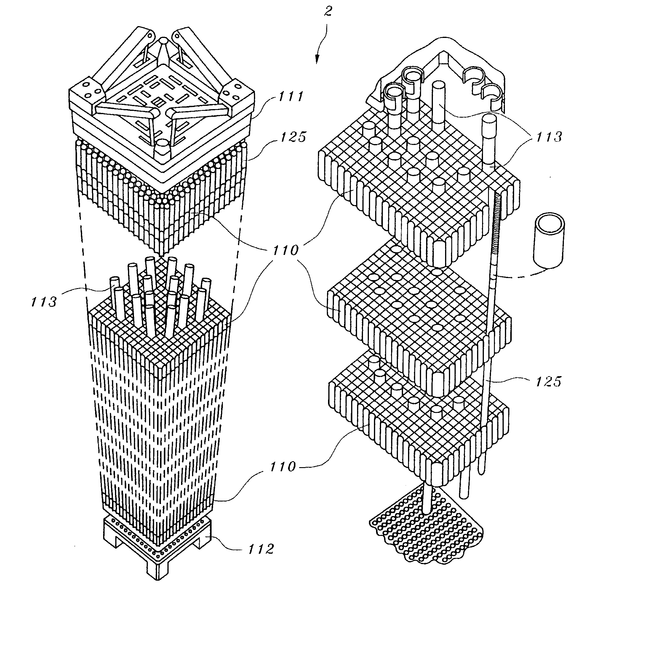
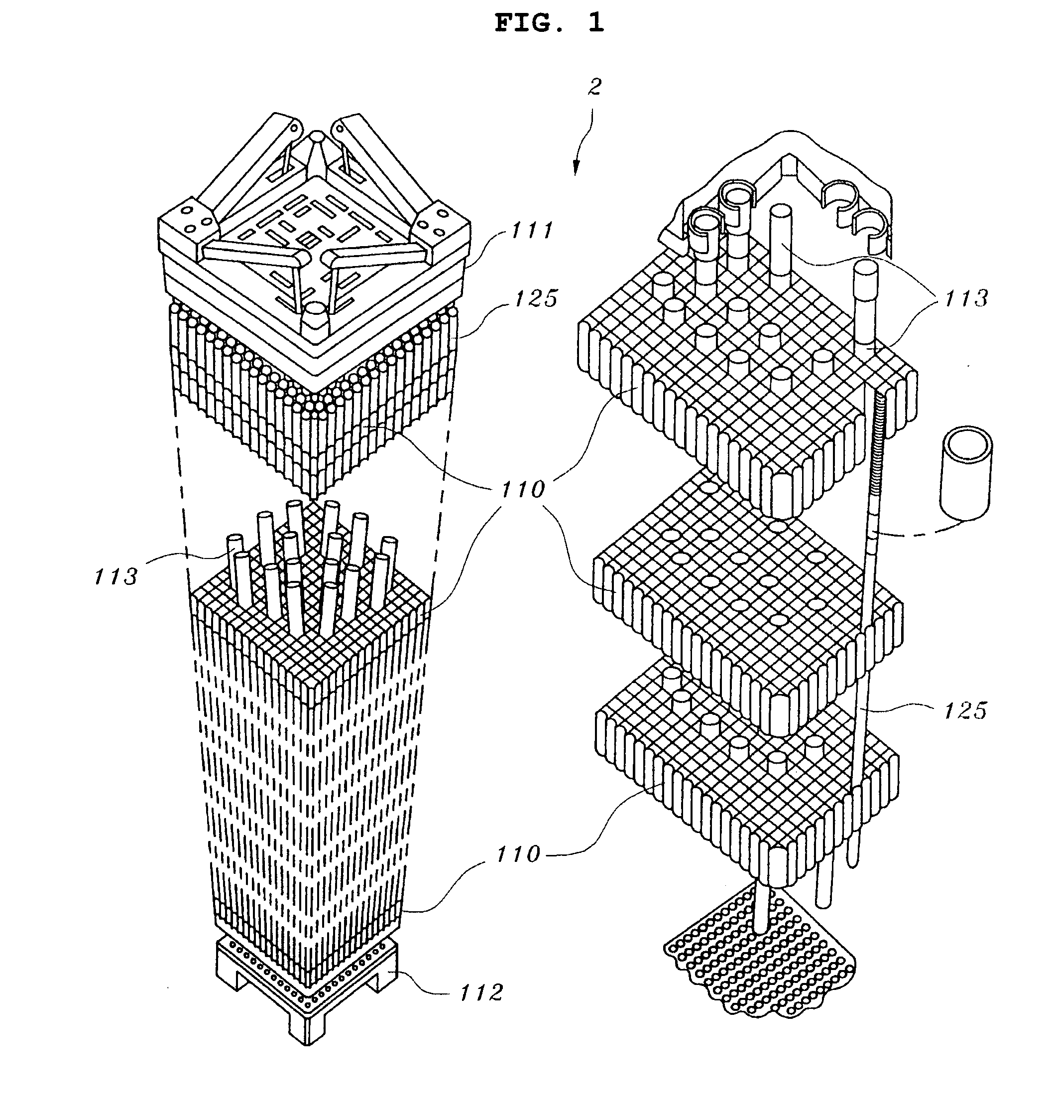
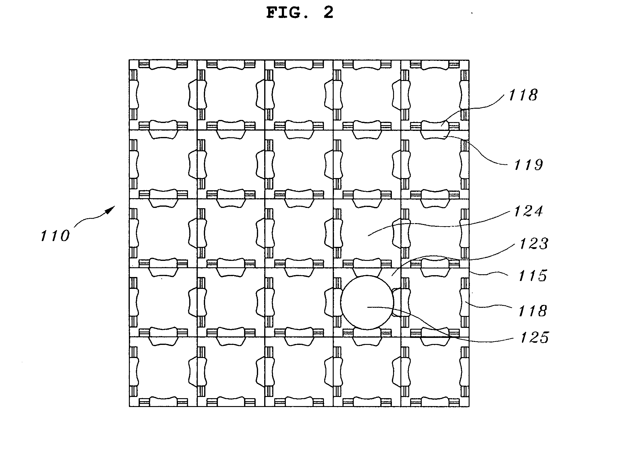
This stress concentration makes the spacer grid spring vulnerable to fatigue, so that each nuclear fuel rod 125 has a high possibility of increasing the fretting wear thereof.
Further, when spring force of the spacer grid spring 118 and dimples 119 of each grid strap 115 is too weak, the nuclear fuel rods 125 cannot be arranged at designated positions, and thereby have a possibility of losing sound supporting performance.
Thus, the coolant channel between the neighboring nuclear fuel rods becomes narrow or is blocked.
As a result, heat generated from the nuclear fuel rods is not effectively transmitted to the coolant, thereby increasing the temperature of the nuclear fuel rods.
However, most concepts for raising this thermal performance are based on the principle that the flow of the coolant flowing around the nuclear fuel rods is very turbulent, the flow has a high Reynolds number.
For this reason, the contact surfaces of the nuclear fuel rods are subjected to local wear, which incur

Method used


Image

  • Spacer grid spring for increasing the conformal contact area with fuel rod
  • Spacer grid spring for increasing the conformal contact area with fuel rod
  • Spacer grid spring for increasing the conformal contact area with fuel rod

Examples


Embodiment Construction

[0045] Reference will now be made in greater detail to an exemplary embodiment of the invention, which is illustrated in the accompanying drawings. Wherever possible, the same reference numerals will be used throughout the drawings and the description to refer to the same or like parts.

[0046]FIG. 6 is a perspective view illustrating a grid strap having a spacer grid spring that increases the conformal contact area with a nuclear fuel rod in accordance with an embodiment of the present invention. FIG. 7 is a front view illustrating a grid strap having a spacer grid spring that increases the conformal contact area with a nuclear fuel rod in accordance with an embodiment of the present invention. FIG. 8 is a plan view illustrating a grid strap having a spacer grid spring that increases the conformal contact area with a nuclear fuel rod in accordance with an embodiment of the present invention. FIG. 9 is a perspective view schematically illustrating one cell of spacer grids made by usi...


PUM


Abstract

A grid strap includes a spacer grid spring that increases the conformal contact area with a fuel rod of a nuclear fuel rod assembly. The shape of the spacer grid spring of the grid strap which is in contact with the fuel rod is optimized, thereby the elasticity of the spacer grid spring contacting the fuel rod is increased, the conformal contact area with a contact portion of the spacer grid spring contacting the fuel rod when the fuel rod is inserted into each cell of a spacer grid is expanded to obtain uniform stress distribution, and excessive plastic deformation of the spacer grid spring can be reduced. Further, magnitude and distribution of contact pressure between the fuel rod and the spacer grid spring are improved, thereby reducing the possibility of fretting wear caused by contact between the fuel rod and the spacer grid spring. The elastic behavior region of the spacer grid spring is expanded, so that the fuel rod can be reliably supported until the lifetime of the fuel rod expires despite changes in the supporting conditions of the fuel rod.

Description

BACKGROUND OF THE INVENTION [0001] 1. Field of the Invention [0002] The present invention relates to spacer grid spring that increases the conformal contact area with a fuel rod and, more particularly, to spacer grid spring that increases the conformal contact area with a fuel rod, in which the spacer grid spring of the grid strap, which is in contact with the fuel rod, is optimized in shape, thereby the elasticity of the spacer grid spring contacting the fuel rod is increased, the conformal contact area with a contact portion of the spacer grid spring contacting the fuel rod when the fuel rod is inserted into each cell of a spacer grid spring is expanded to realize uniform stress distribution, and excessive plastic deformation of the spacer grid spring can be reduced, and in which magnitude and distribution of contact pressure between the fuel rod and the spacer grid spring are improved, thereby reducing the possibility of fretting wear caused by contact between the fuel rod and th...

Claims


Application Information

Patent Timeline
IPC IPC(8): G21C3/34
CPCG21C3/356G21Y2002/201Y02E30/40G21Y2002/303G21Y2004/30G21Y2002/206Y02E30/30G21C3/34
Inventor SONG, KEE-NAMYOON, KYUNG-HOSONG, KUN-WOOLEE, KANG-HEEPARK, KYUNG-JIN
Owner KOREA ATOMIC ENERGY RES INST
Why Eureka
Try Eureka