Field Deployable Power Distribution system and Method Thereof

a power distribution system and field technology, applied in adaptive control, process and machine control, instruments, etc., can solve the problems of unnecessary casualties and deaths, many roads along the route, and high cost of additional capabilities, so as to maximize the utilization of electrical energy and optimize the use of available electrical power sources.

Inactive Publication Date: 2007-10-18
PROTON ENERGY SYST
View PDF10 Cites 36 Cited by
  • Summary
  • Abstract
  • Description
  • Claims
  • Application Information

AI Technical Summary

Benefits of technology

[0013]A method for optimizing the use of available electrical power sources is also provided. The method includes the steps of first determining the amount of hydrogen gas held in storage. The amount of available electrical energy available from a regenerative fuel cell is then determined. The amount of available electrical energy is compared to a plurality of discrete load circuits coupled to the regenerative fuel cell. Finally, one or more of said plurality of discrete load circuits is selectively disconnected based on a predetermined prioritization of the discrete load circuits and an expected level of electrical usage whereby the selection process maximizes the utilization of the electrical energy while maintaining mission critical load circuits.

Problems solved by technology

The commanders radioed turn-by-turn directions to the soldiers only to discover that many roads along the routes were impassable due to enemy obstructions.
A common problem encountered by modern armed forces during the confusion of battle, as evidenced during the Gulf War, is the phenomenon known as “friendly fire” in which forces accidentally fire on their own troops causing unnecessary casualties and fatalities.
Instances of friendly fire often involve aircraft or helicopters accidentally firing on their own ground troops.
However, the additional capabilities come at a price.
This added weight has a detrimental effect on the mobility of soldiers.

Method used


Image

  • Field Deployable Power Distribution system and Method Thereof
  • Field Deployable Power Distribution system and Method Thereof
  • Field Deployable Power Distribution system and Method Thereof

Examples


Embodiment Construction

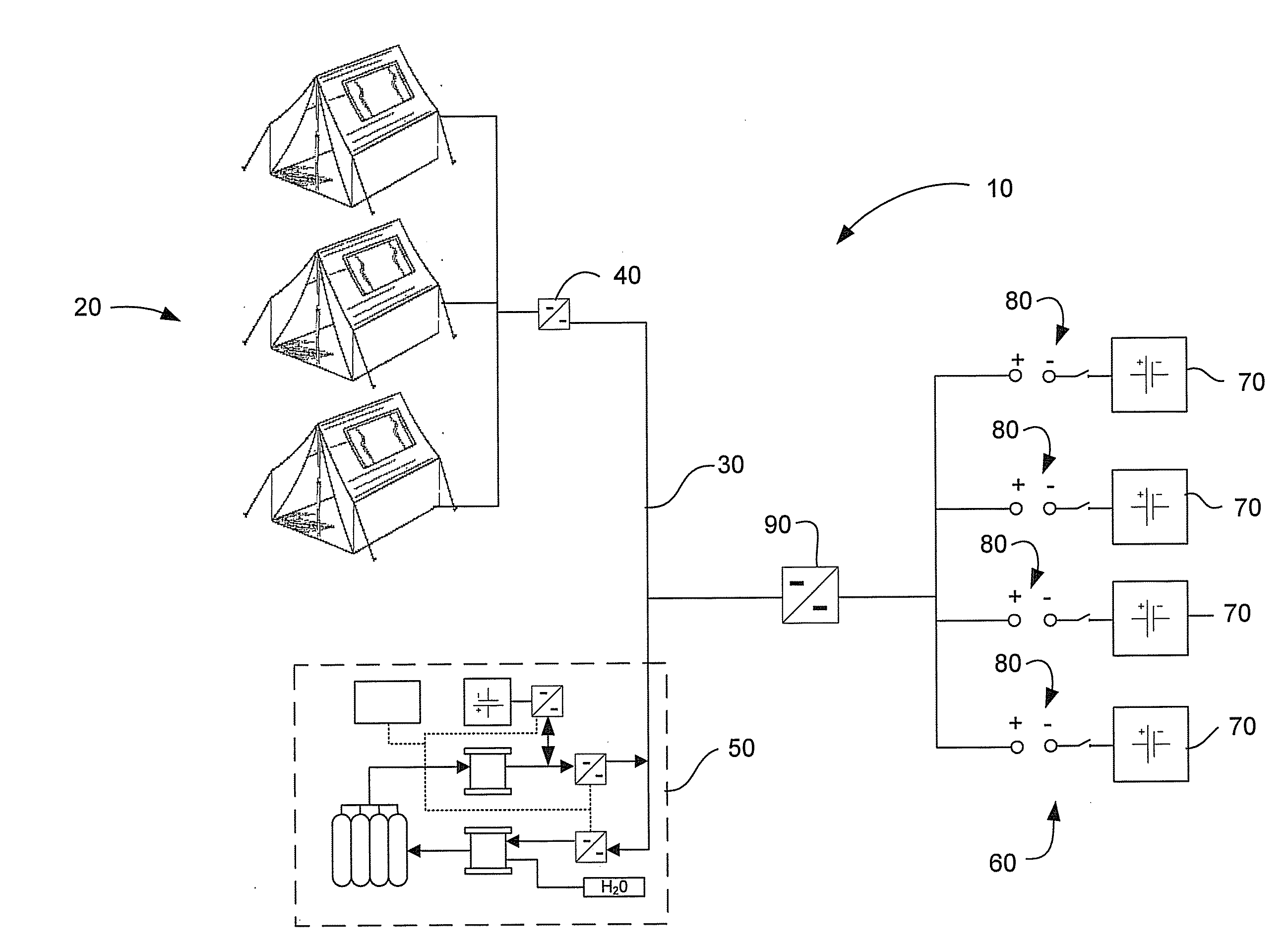
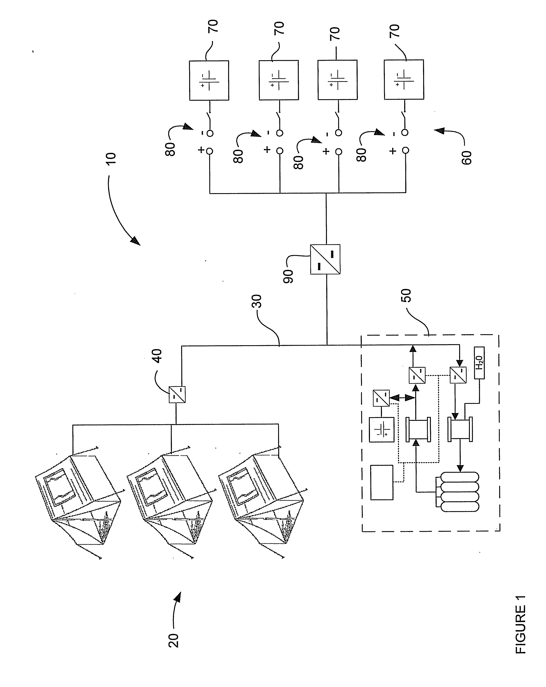
[0020]Traditionally, electrical power distribution systems that were deployed in field operation camps were connected to generators powered internal combustion engines. The generators or “gensets” provided all the electrical power needs for the operation camp in that location. However, gensets created several problems, especially when utilized in military field operations where a certain degree of stealth was required. First, gensets are typically fueled by hydrocarbon based fuel, such a diesel, natural gas or JP-8. This need for fuel created logistical issues, and the operations needed to be positioned such that the logistical fuels could be delivered on a regular basis. A second problem created by the gensets is that since they burned fuel to generate the mechanical energy to rotate the generator, the genset often created heat and exhaust. While the heat could be utilized in the operations, it often also created a “signature” that could be detected by opposing forces to identify t...


PUM

PropertyMeasurementUnit
pressuresaaaaaaaaaa
poweraaaaaaaaaa
electrical poweraaaaaaaaaa

Abstract

A system for providing field deployable electrical power distribution is provided. The system includes a plurality of power sources providing electrical power to meet the electrical needs of a field operations camp. The power sources include at least one regenerative fuel cell that is arranged to provide a electrical power when renewable energy sources are unavailable. Also provided is at least one generator and one regenerative fuel cell electrically connected to the plurality of loads. Also provided is a plurality of power converters, each of the plurality of power converters being electrically connected between the at least one generator and regenerative fuel cell and one of the plurality of loads. An arrangement is also included for providing a high availability battery charging station.

Description

FIELD OF INVENTION[0001]This disclosure relates generally to a system for providing a power system incorporating multiple power sources for use in field deployable operations, and especially relates to systems incorporating renewable power sources as a source for recharging batteries.BACKGROUND OF THE INVENTION[0002]With the collapse of the Soviet Union, the government officials who operated the former communist state allowed the global proliferation of modern military equipment by selling off equipment through alternative channels of commerce. Through these black-market channels, even insignificant warlord chieftains and terrorists were granted access to weaponry that can disrupt the operations of some of the world's most sophisticated armies. In October 1993 U.S. Army Rangers raided a compound in Mogadishu, Somalia. The U.S. was responding to seizures of humanitarian supplies by local militia who were seeking to exploit the charity of the international community for their own pecu...

Claims


Application Information

Patent Timeline
Patent Type & Authority Applications(United States)
IPC IPC(8): H01M8/00
CPCH01M8/04298H01M8/04619H01M8/04626H01M8/04888H01M8/0494C25B9/08H01M16/006H02J7/35H02J2001/004Y02E60/50H01M8/04955C25B9/19H02J2300/30Y02E60/10Y02P20/133
Inventor SPANER, MICHAEL AARON
Owner PROTON ENERGY SYST
Why Eureka
Try Eureka