Supercharge Your Innovation With Domain-Expert AI Agents!

Computer-aided method of obtaining a ply model of a composite component

Active Publication Date: 2007-10-18
AIRBUS OPERATIONS SL
View PDF6 Cites 38 Cited by
  • Summary
  • Abstract
  • Description
  • Claims
  • Application Information

AI Technical Summary

Benefits of technology

[0015] One aim of this method is to save the interoperativity gap existent from when the stress results are given to design until design produces a ply model.
[0016] Another aim of this method is to provide a simple and efficient way of working that can be used to perform an interactive ply engineering process and can be used to automatically obtain plies wireframe geometry data in order to obtain a preliminary ply model to be displayed on any CAD program. Therefore a considerable amount of time and effort can be saved when creating ply models, in particular in the staggering process which has so far been a very tedious and time consuming task.

Problems solved by technology

So far the process of generating such ply CAD models has been a tedious and elaborate procedure involving a large amount of repetitive manual work with the subsequent risk of mistake.

Method used


Image

  • Computer-aided method of obtaining a ply model of a composite component
  • Computer-aided method of obtaining a ply model of a composite component
  • Computer-aided method of obtaining a ply model of a composite component

Examples


Embodiment Construction

[0026] We will now describe an embodiment of this invention for obtaining a preliminary CAD ply model for a HTP skin of an aircraft using Visual Basic as programming language and showing the results in Excel worksheets.

[0027] In step a) the stacking sequence is obtained from ARPA, a stress program used to calculate skins behaviour under certain load conditions. The output file obtained from ARPA is a file containing, among other data, the stacking sequence for each panel, defined in this case by stringers and ribs as illustrated in the following Table 1.

TABLE 1Stacking Sequence (Orientation &Panel No.Stringer Id.Rib Id.Material)1STR1R01(45 / −45 / 90 / 0 / 90 / −45 / 45)2STR2R01(45 / −45 / 90 / 0 / 90 / −45 / 45 / 90)3STR3R01(45 / −45 / 90 / 0 / 90 / −45 / 45 / 90 / 45). . .. . .. . .. . .

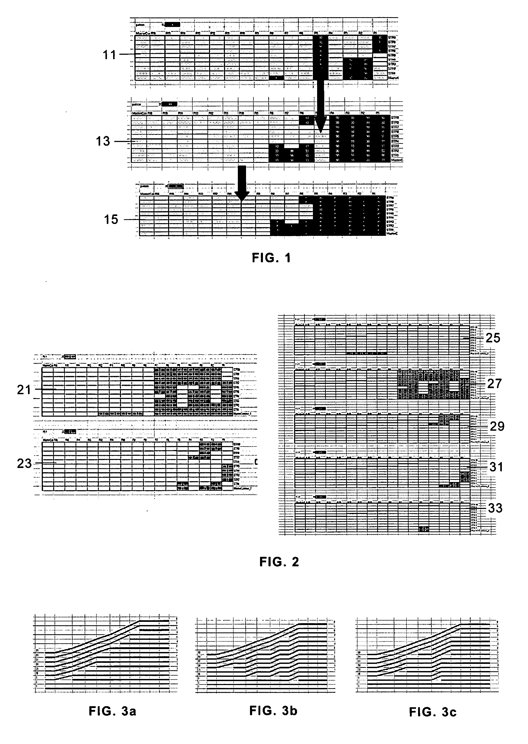
[0028] In step b) the ARPA file is processed to obtain a stacking table containing, among other data, the data schematically shown in the following table

[0029] In step c) the ARPA file is processed to obtain a grid table containing th...


PUM

PropertyMeasurementUnit
Symmetryaaaaaaaaaa

Abstract

A computer-aided method of obtaining a preliminary ply model of a composite component to be used in the manufacture of industrial parts by stacking and joining a plurality of plies of composite materials, comprising the following steps: a) obtaining from stress calculations a ply stacking sequence for the component subdivided into panels; b) automatically generating a stacking table containing the ply sequence for each different zone (defined by its ply sequence); c) automatically generating a grid table; d) optimising said stacking table; e) performing the plies drop-off distribution by means of a tool that allows carrying out said distribution automatically according to a predetermined staggering rule; f) obtaining an output table containing the data required for representing the ply model in a CAD program.

Description

FIELD OF THE INVENTION [0001] The present invention refers to a method of obtaining a ply model of a composite component, and more particularly to a computer-aided method of obtaining a preliminary ply model of a composite component able to be used by a CAD program. BACKGROUND OF THE INVENTION [0002] In some engineering fields there is a large tendency to increase the amount of components made from composite materials, for instance in the aeronautical field: wing skins, covers, fuselage sections are components that may be manufactured using composites materials. [0003] These components are generally made from carbon fibre and consist of different layers (plies) of composite material laid in different orientations in order to obtain a laminate (stacking). [0004] These components are divided into different zones and each zone has its own thickness and therefore its own laminate. The difference in thickness between different zones generates ply drop-offs which need to be organised and ...

Claims


Application Information

Patent Timeline
IPC IPC(8): G06F19/00
CPCB29C70/54G06F17/50G06F17/5009G06F2217/44Y10T428/24926Y10T428/265Y10T428/24992Y10T428/24446Y10T428/24826Y02T50/433G06F30/00G06F30/20G06F2113/26Y02P90/02Y02T50/40
Inventor MENAYO, GUILLERMO MARTINQUERO, ANTONIO BOLINCHES
Owner AIRBUS OPERATIONS SL
Features
  • R&D
  • Intellectual Property
  • Life Sciences
  • Materials
  • Tech Scout
  • Unparalleled Data Quality
  • Higher Quality Content
  • 60% Fewer Hallucinations
Learn More