Electron emission display

Inactive Publication Date: 2007-10-25
SAMSUNG SDI CO LTD
View PDF3 Cites 2 Cited by
  • Summary
  • Abstract
  • Description
  • Claims
  • Application Information

AI Technical Summary

Benefits of technology

[0015]Aspects of the present invention provide an electron emission display that can (a) improve (or heighten) a screen luminance, color purity, and color reproduction rate, (b) enhance (or increase) an adhering force of an anode electrode to the second substrate, and / or (c) maximize a light reflection efficiency by optimizing (or increasing) a distance between the anode electrode and the phosphor layer.

Problems solved by technology

Therefore, when the aluminum is directly deposited on the surface of the phosphor layer, the anode electrode is directly affected by a roughness of the phosphor particles and a desired light reflection effect may not be obtained.
As a result, the screen luminance may not be enhanced.
That is, since the anode electrode contacts the second substrate only at its periphery, the contacting area of the anode electrode with the second substrate may be too small to provide for a sufficient adhering force to the second substrate.
As a result, when the interlayer is not effectively discharged to an external side through fine pores of the anode electrode during the baking process, the anode electrode may swell to a point in which it is partly delaminated or damaged by contact with spacers of the display.
Since the light may not be effectively reflected on the delaminated or damaged portion of the anode electrode, a luminance of a portion of the phosphor layer, which corresponds to the delaminated or damaged portion of the anode electrode, may be deteriorated, thereby adversely affecting color purity.
Therefore, when the visible light, which is emitted from a phosphor layer of a specific pixel toward the first substrate, is reflected back to the second substrate by the anode electrode, the visible light may be scattered to a different color phosphor layer of an adjacent pixel, thereby further deteriorating the color purity and color reproduction rate of the screen.

Method used


Image

  • Electron emission display
  • Electron emission display
  • Electron emission display

Examples


Embodiment Construction

[0029]In the following detailed description, only certain exemplary embodiments of the present invention are shown and described, by way of illustration. As those skilled in the art would recognize, the invention may be embodied in many different forms and should not be construed as being limited to the embodiments set forth herein. Also, in the context of the present application, when an element is referred to as being “on” another element, it can be directly on the another element or be indirectly on the another element with one or more intervening elements interposed therebetween. Like reference numerals designate like elements throughout the specification.

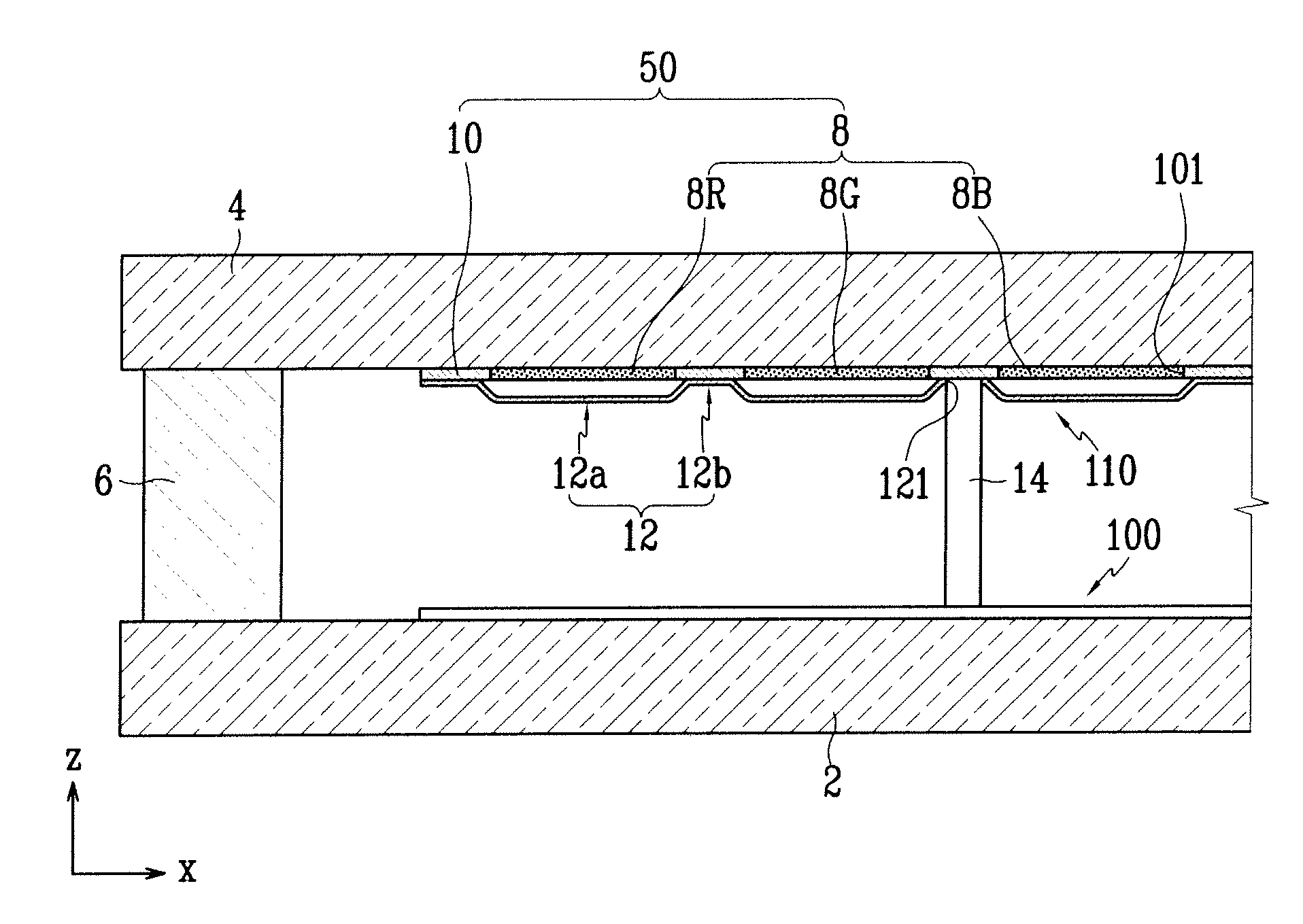
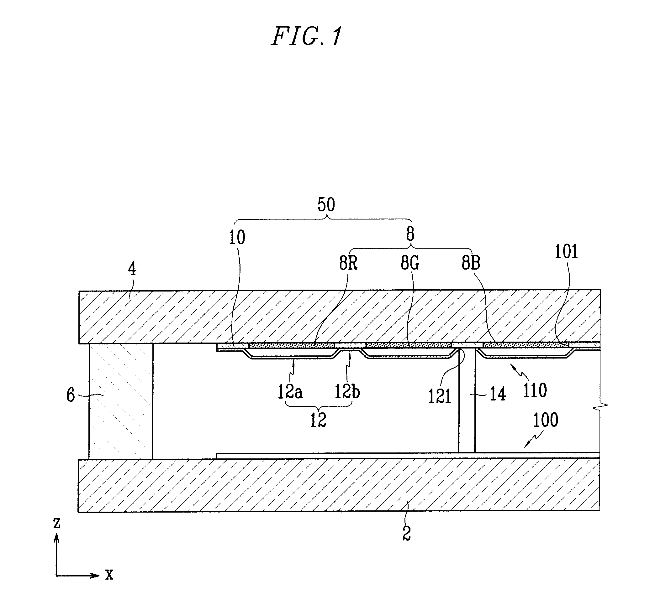
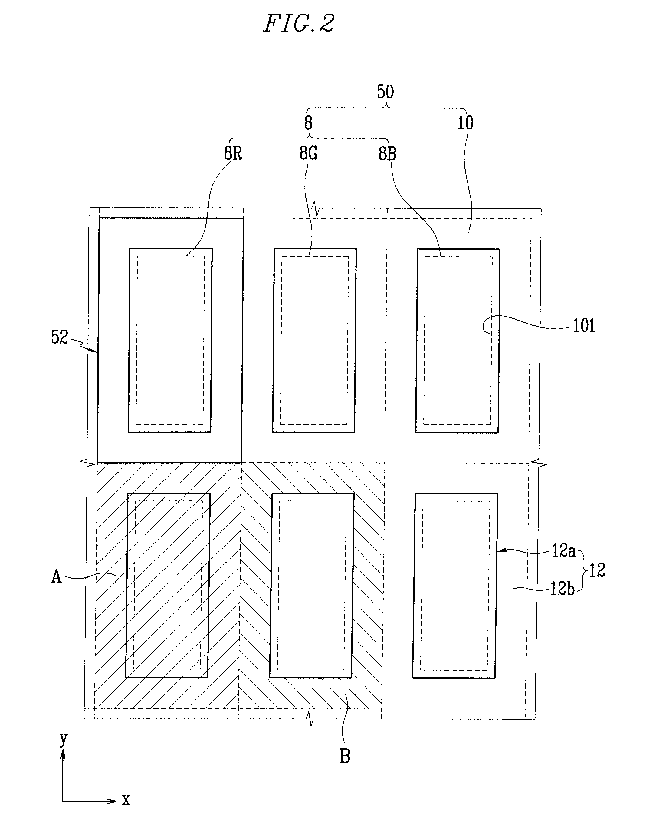
[0030]FIG. 1 is a schematic sectional view of an electron emission display according to an exemplary embodiment of the present invention, and FIG. 2 is a partial top view of a light emission unit of the electron emission display of FIG. 1.

[0031]Referring to FIG. 1, an electron emission display includes first and second substrat...


PUM


Abstract

An electron emission display is provided including first and second substrates facing each other. The second substrate has a plurality of pixel regions defined thereon. A plurality of electron emission elements are disposed on the first substrate. A phosphor screen including phosphor and black layers are formed on a surface of the second substrate. An anode electrode formed of metal is located on surfaces of the phosphor and black layers. The anode electrode includes a spaced portion corresponding to the phosphor layers and spaced apart from the phosphor screen, and includes contact portions contacting the phosphor screen, and satisfies the condition 0.05≦B / A≦0.8, where A indicates an area of one of said pixel regions defined on the second substrate and B denotes an area occupied by one of the contact portions in the one of said pixel regions.

Description

CROSS-REFERENCE TO RELATED APPLICATION[0001]This application claims priority to and the benefit of Korean Patent Application No. 10-2006-0035825, filed in the Korean Intellectual Property Office on Apr. 20, 2006, the entire content of which is incorporated herein by reference.BACKGROUND OF THE INVENTION[0002]1. Field of the Invention[0003]The present invention relates to an electron emission display and, more particularly, to an electron emission display having a contact area between an anode electrode and a black layer.[0004]2. Description of Related Art[0005]Electron emission elements can be classified into those using hot cathodes as an electron emission source, and those using cold cathodes as an electron emission source.[0006]There are several types of cold cathode electron emission elements, including field emitter array (FEA) type electron emission elements, metal-insulator-metal (MIM) type electron emission elements, metal-insulator-semiconductor (MIS) type electron emission...

Claims


Application Information

Patent Timeline
IPC IPC(8): H01J1/62
CPCH01J29/085H01J1/30
Inventor LEE, SU-KYUNGYOO, SEUNG-JOONPARK, ZIN-MINKANG, JUNG-HOLEE, WON-IL
Owner SAMSUNG SDI CO LTD
Why Eureka
Try Eureka