Electric wire with terminal, and method for manufacturing same
- Summary
- Abstract
- Description
- Claims
- Application Information
AI Technical Summary
Benefits of technology
Problems solved by technology
Method used
Image

Examples
second embodiment
[0083]Note that, as a second embodiment, the release promoting member 50 can be formed integrally with the crimp terminal 10.
[0084]FIG. 13 shows part of a manufacturing process of an electric wire with a terminal according to the second embodiment. In this crimp terminal 130, a bridge-shaped frame portion 150 which corresponds to the release promoting member is provided integrally with the connection portion 15 between the electrical connection portion 11 and the conductor crimp portion 12. The frame portion 150 plays the same role as the release promoting member 50 in the embodiment described previously.
[0085]Here, the type of the crimp terminals 10 and 130 may be a male-type terminal or a female-type terminal.
third embodiment
[0086]the present invention will then be described with reference to drawings.
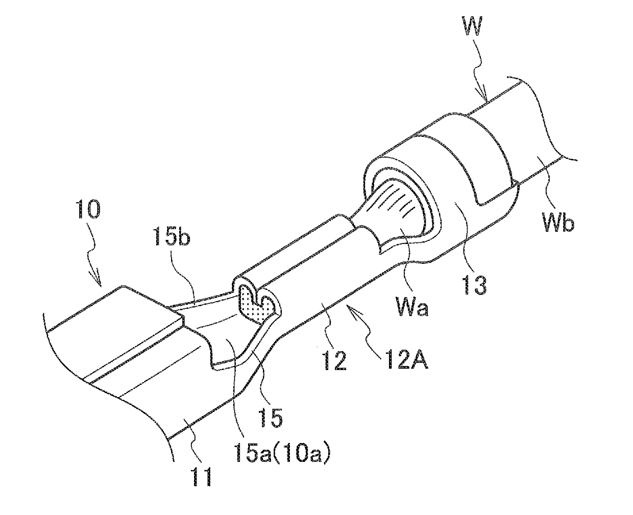
[0087]As shown in FIGS. 14A and 14B, an electric wire with a terminal 210 includes an aluminum electric wire (electric wire) 211 and a female-type crimp terminal 220 which is made of copper or a copper alloy. The aluminum electric wire 211 includes a core wire (conductor) 212 which is made of aluminum or an aluminum alloy and an insulating coating 213 which is made of insulating resin to coat the core wire 212. The crimp terminal 220 includes a terminal connection portion (electrical connection portion) 221 which is connected to an unillustrated mating terminal, a core wire crimp portion 223 which is crimped to the core wire 212 exposed from the end portion of the aluminum electric wire 211 and a coating crimp portion 225 which is crimped to the insulating coating 213 at the end of the aluminum electric wire 211.
[0088]Further, as shown in FIGS. 14A, 14B and 17, an anti-corrosive material (anti-corrosive re...
fourth embodiment
[0096]FIG. 19 is a development view of a crimp terminal used in an electric wire with a terminal according to the present invention.
[0097]In the fourth embodiment, in the inner surface 222c of the bottom plate portion 222a of the coupling portion 222 in a crimp terminal 220′, a plurality of vertical grooves (grooves) 226 for close contact with resin is formed in a plurality of rows (three rows each with three grooves in the present embodiment) at a predetermined distance apart parallel to each other in a direction perpendicular to the longitudinal direction of the crimp terminal 220. Note that, since the other configurations are the same as those in the third embodiment, the same constituent members are identified with the same reference signs, and the detailed description thereof will be omitted.
[0098]In the fourth embodiment also, as in the third embodiment, a plurality of rows of a plurality of vertical grooves 226 for close contact with resin is formed in the inner surface 222c ...
PUM
 Abstract
Description
Claims
Application Information
 - R&D Engineer
- R&D Manager
- IP Professional
- Industry Leading Data Capabilities
- Powerful AI technology
- Patent DNA Extraction
Browse by: Latest US Patents, China's latest patents, Technical Efficacy Thesaurus, Application Domain, Technology Topic.
© 2024 PatSnap. All rights reserved.Legal|Privacy policy|Modern Slavery Act Transparency Statement|Sitemap