Method of manufacturing inkjet printhead and inkjet printhead manufactured using the same

Inactive Publication Date: 2009-03-19
S PRINTING SOLUTION CO LTD
View PDF3 Cites 6 Cited by
  • Summary
  • Abstract
  • Description
  • Claims
  • Application Information

AI Technical Summary

Benefits of technology

[0011]The present general inventive concept provides a simple method of manufacturing an inkjet printhead using an excellent channel forming material, in which a glue layer to enhance an adhesive force between a substrate and a channel forming layer is not used.

Problems solved by technology

The entire manufacturing process is complex and expensive.

Method used


Image

  • Method of manufacturing inkjet printhead and inkjet printhead manufactured using the same
  • Method of manufacturing inkjet printhead and inkjet printhead manufactured using the same
  • Method of manufacturing inkjet printhead and inkjet printhead manufactured using the same

Examples


preparation example 1

Preparation of Negative Photoresist Composition

[0088]30 g of xylene (produced by Samchun Chemical Co.), 2 g of glycidoxypropyltrimethoxysilane (produced by Sigma-Aldrich), and 2 g of SP-172 (produced by Asahi Denka Korea Chemical Co.) were added to a jar to prepare a resist solution. Then, 40 g of EPON SU-8 (produced by Shell Chemical Co.) was added to the jar, and then the resultant solution was mixed using an impeller for about 24 hours, thereby preparing a negative photoresist composition.

example 1

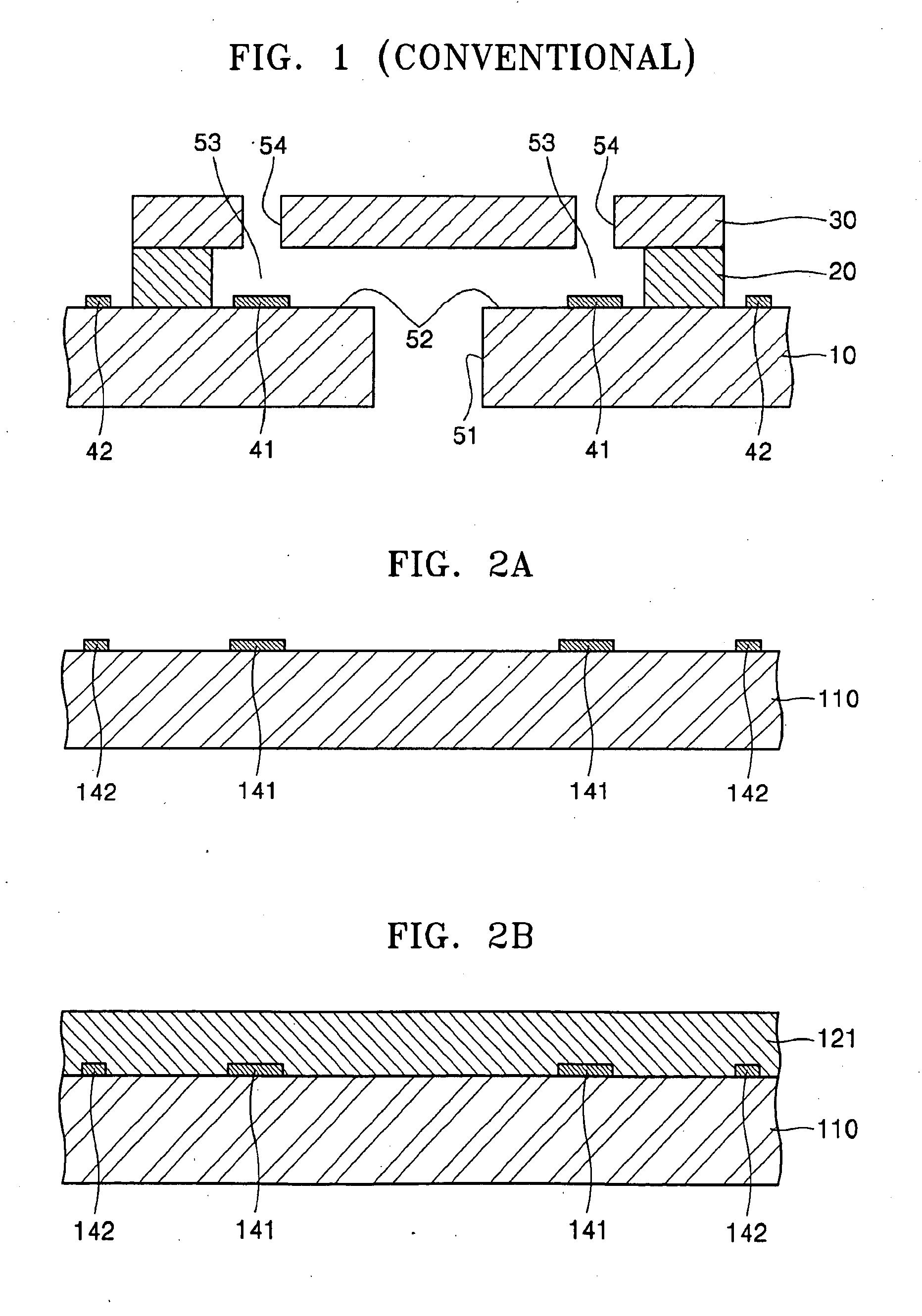
[0089]A tantalum nitride heater pattern 141 having a thickness of about 500 Å and an electrode pattern 142 formed of an AlSiCu alloy (Si and Cu each in an amount of 1 wt. % or less) having a thickness of about 500 Å were formed on a 6-inch silicon wafer 110 using a conventional sputtering process and a photolithography process (see FIG. 2A).

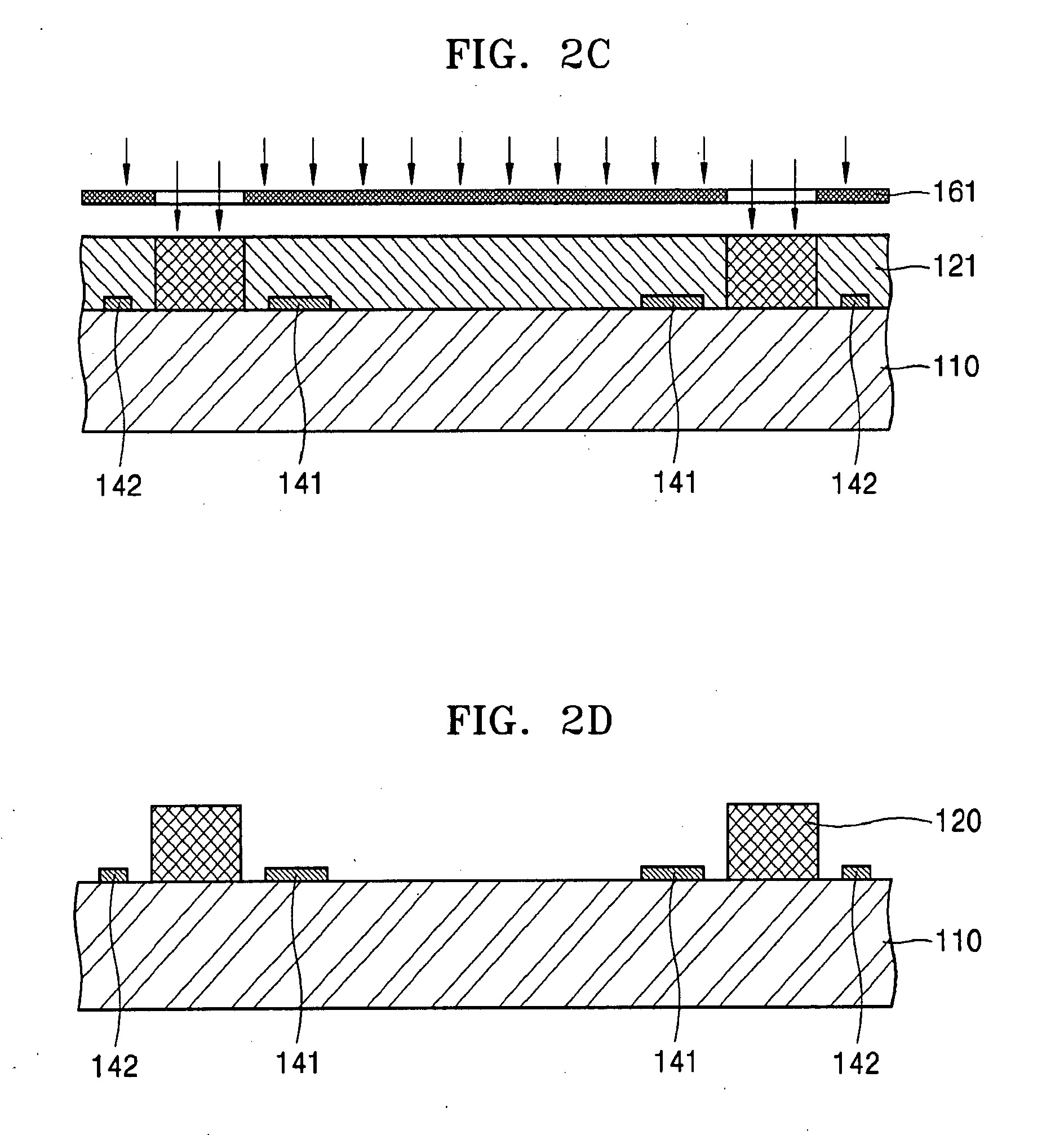
[0090]Then, as illustrated in FIG. 2B, the negative photoresist composition prepared according to Preparation Example 1 was spin coated on the surface of the substrate (silicon wafer) 110 on which the tantalum nitride heater pattern 141 and the electrode pattern 142 were formed, with a rotation speed of 2000 rpm for 40 seconds, and then baked at 95° C. for 7 minutes to form a first negative photoresist layer 141 having a thickness of about 10 μm. Then, as illustrated in FIG. 2C, the first negative photoresist layer 141 was exposed to i-line UV light using a first photomask 161 having a predetermined ink chamber pattern and a restrictor pattern. I...


PUM


Abstract

A method of manufacturing an inkjet printhead using a channel forming material, in which a glue layer to enhance an adhesive force between a substrate and a channel forming layer is not required.

Description

CROSS-REFERENCE TO RELATED APPLICATIONS[0001]This application claims priority under 35 U.S.C. §119(a) from Korean Patent Application No. 10-2007-0095448, filed on Sep. 19, 2007, in the Korean Intellectual Property Office, the disclosure of which is incorporated herein in its entirety by reference.BACKGROUND OF THE INVENTION[0002]1. Field of the Invention[0003]The present general inventive concept relates to a method of manufacturing an inkjet printhead and an inkjet printhead manufactured using the method, and more particularly, to a simple method of manufacturing an inkjet printhead using a channel forming material, in which a glue layer to enhance an adhesive force between a substrate and a channel forming layer is not required, and an inkjet printhead manufacturing using the method.[0004]2. Description of the Related Art[0005]Inkjet printheads eject tiny droplets of printing ink to a predetermined portion of a to-be-printed target sheet so as to produce a predetermined color imag...

Claims


Application Information

Patent Timeline
IPC IPC(8): B44C1/22B41J2/04
CPCB41J2/1603B41J2/1628B41J2/1631B41J2/1646B41J2/1639B41J2/1642B41J2/1645B41J2/1632B41J2/1404B41J2/1626
Inventor PARK, BYUNG-HAHA, YOUNG-UNGPARK, SUNG-JOONHAN, JEONG-WUK
Owner S PRINTING SOLUTION CO LTD
Why Eureka
Try Eureka