Lighted Display Case with Remote Light Source

a technology of remote light source and display case, which is applied in the field of lighted display case with a remote light source, can solve the problems halogen or incandescent lamps similarly have the disadvantage of directing a large amount of heat into the display area, and achieve the effect of less electrical power

Inactive Publication Date: 2007-10-25
ENERGY FOCUS INC +1
View PDF7 Cites 14 Cited by
  • Summary
  • Abstract
  • Description
  • Claims
  • Application Information

AI Technical Summary

Benefits of technology

[0006] The disclosed invention provides the foregoing benefits and others such as requiring less electrical power to provide comparable amounts of light even apart from the maintenance and energy transport consideration outlined above.

Problems solved by technology

Such lamps have various disadvantages for lighting tightly confined spaces.
When taken together with their ballasts, the complete lighting system can produce a significant amount of heat, especially when confined in an enclosure.
Halogen or incandescent lamps similarly have the disadvantages of directing a large amount of heat into the display area.
Although a halogen lamp is often accompanied by a special dichroic reflector which concentrates visible light but not infrared light in the forward direction, the confined nature of a display case often ends up trapping this undirected infrared energy anyway.
This usually results in an excessive heat buildup or the necessity to remove this heat by energy-demanding means such as air conditioning or forced air convection.
Even when no special measures are taken to transport the unneeded heat away, the heat is usually an inconvenience at best and a nuisance at worst to the customers or patrons who must view the contents of the case.
Fluorescent tubes, while more energy-efficient than tungsten-halogen lamps, have other disadvantages as well.
They are fragile and contain hazardous substances such as mercury and phosphors.
If broken, the glass shards are a severe safety hazard.
Due to the manner in which such tubes must be mounted in the typical display case, changing the tubes can be an awkward and labor-intensive operation requiring the careful removal and reinsertion of a fragile item in a confined space.
As a result, they need to be replaced much more frequently than their fluorescent counterparts resulting in either an uneven lighting situation when they fail, or a costly manual maintenance operation to replace the failed lamps with great promptness.

Method used


Image

  • Lighted Display Case with Remote Light Source
  • Lighted Display Case with Remote Light Source
  • Lighted Display Case with Remote Light Source

Examples


Embodiment Construction

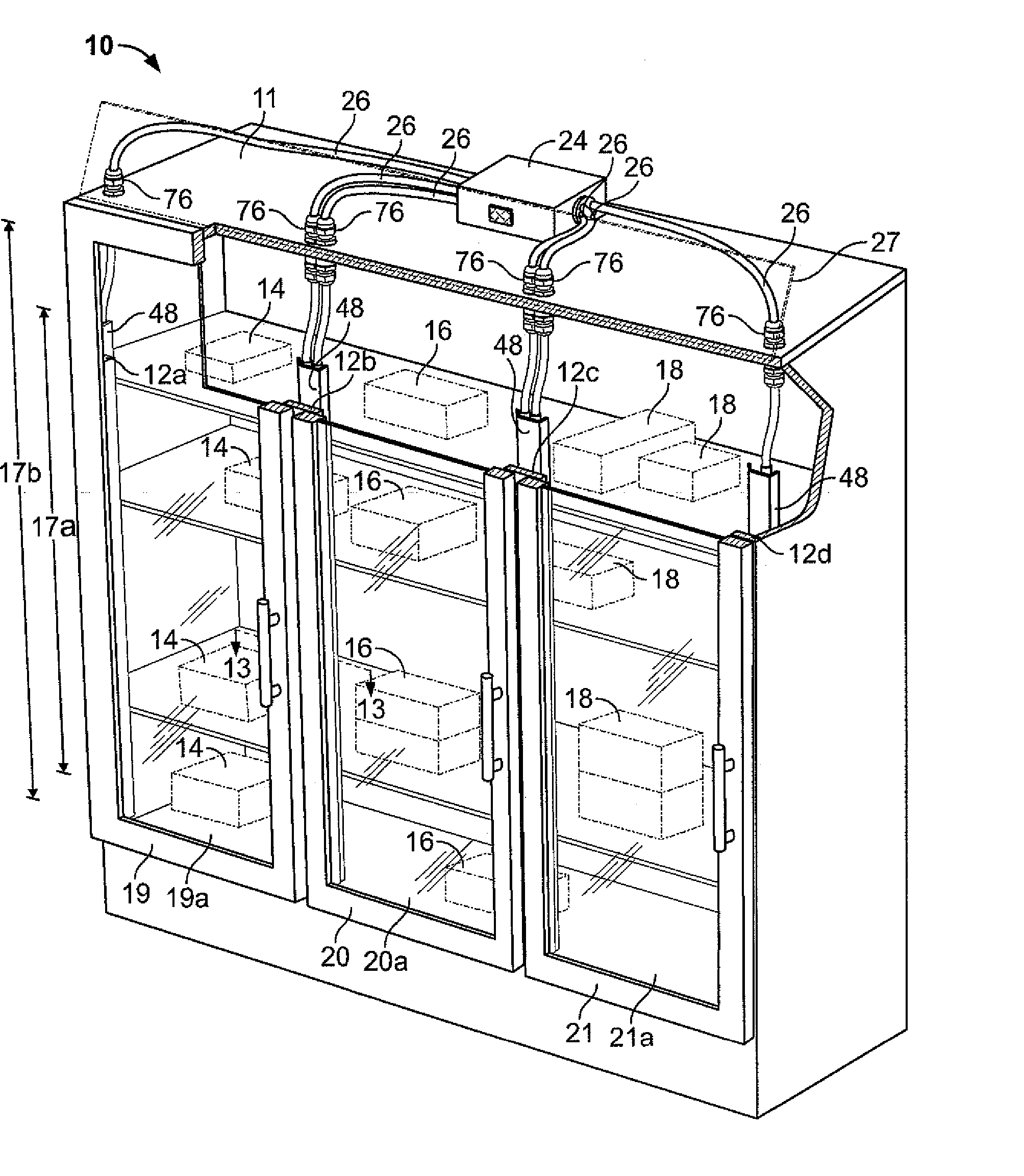
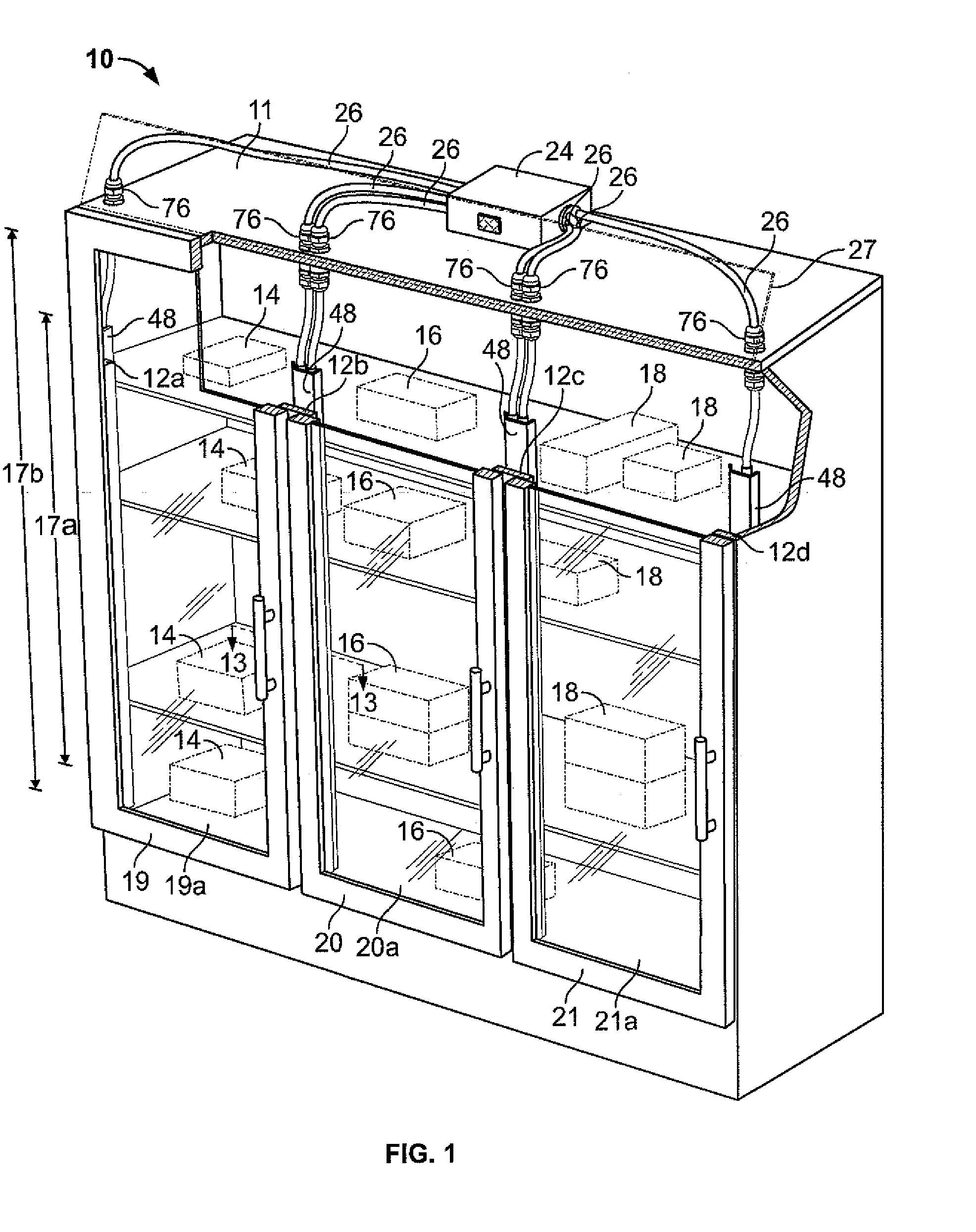
[0042]FIG. 1 shows a display case 10 for illuminating contents of the case, such as contents 14, 16 and 18. Case 10 includes a closed container 11 and fiber optic luminaires (not shown) behind structural members 12a-12d for achieving the foregoing purpose of illumination. The term “fiber optic” luminaire is intended to cover an acrylic rod luminaire that receives light directly from a light source as well as indirectly through a fiber optic cable or other structure. Preferably, case 10 includes doors 19, 20 and 21 having respective view ports 19a, 20a and 21a. These view ports preferably comprises transparent windows, as shown, but could comprise a doorway when doors 19, 20 or 21 are opened for viewing contents of the display case. The luminaires extend vertically over dimension 17a, whereas the maximum dimension of a view port (e.g., 19a) is dimension 17b. As can be seen dimension 17a is at least the majority of dimension 17b. Rather than including windows 19a, 20a and 21a on doors...


PUM


Abstract

Lighted display case with remote light source comprises a container having contents for display. A solid fiber optic luminaire is at least partially mounted within the container, having an elongated side-light emitting portion for emitting light from the side of the luminaire onto contents in an interior of the display case. The side-light emitting portion comprises an extractor of light arranged to preferentially extract light from the luminaire and direct the light to at least one target area of said contents. The portion may be rotatable about its own longitudinal axis. A single side-light emitting portion may be arranged to illuminate a target area on one of its lateral sides, and another target area on another lateral side. A single lamp may provide light to first and second luminaires arranged to illuminate a target area on one of its lateral sides, and another target area on another lateral side.

Description

FIELD OF THE INVENTION [0001] The present invention relates to a lighted display case with a remote light source. More particularly, the invention relates to such a display case in which light for illuminating contents of the case is provided by a fiber optic luminaire. BACKGROUND OF THE INVENTION [0002] Traditional display cases used to display retail merchandise or items of value such as in a museum often employ fluorescent or (filamented) halogen lamps to light the items. Such lamps have various disadvantages for lighting tightly confined spaces. Among these is the fact that fluorescent tubes emit light in all directions and emit moderate levels of ultraviolet light. When taken together with their ballasts, the complete lighting system can produce a significant amount of heat, especially when confined in an enclosure. Halogen or incandescent lamps similarly have the disadvantages of directing a large amount of heat into the display area. Although a halogen lamp is often accompani...

Claims


Application Information

Patent Timeline
Patent Type & Authority Applications(United States)
IPC IPC(8): A47F11/10
CPCA47F3/001
Inventor BUELOW, ROGERDAVENPORT, JOHNCASSARLY, WILLIAMDAVENPORT, THOMASFRANKIEWICZ, GREGORYJENSON, CHRISCAYWOOD, ROBERT
Owner ENERGY FOCUS INC
Why Eureka
Try Eureka