
Transceiver

a transceiver and transceiver technology, applied in waveguides, waveguide types, instruments, etc., can solve the problems of difficult to process sub-millimeter signals using components developed for microwave circuitry or components, difficult to develop circuit components and circuit structures to process such signals that exhibit both electrical and optical behavior, and difficult to process signals with wavelengths of 1 millimeter or less

Active Publication Date: 2007-10-25
THRUVISION LTD +1
View PDF11 Cites 7 Cited by
  • Summary
  • Abstract
  • Description
  • Claims
  • Application Information

AI Technical Summary

Benefits of technology

"The present invention is a transceiver that can process signals of different frequency ranges. It can handle sub-millimeter signals as well as signals with wavelengths of one millimeter or more. The transceiver has a mixer / filter assembly and a filter circuit within a block. The transceiver can operate in two modes: passive mode and active mode. In the passive mode, the transceiver can receive and process signals from objects and people to generate images. In the active mode, the transceiver can simultaneously transmit and receive signals. The reception of signals can be passive or not. The transceiver has a unique design with multiple cavities and a filter circuit. The technical effects of this invention are its ability to process signals of different frequency ranges and its versatility in transmitting and receiving signals simultaneously or passively."

Problems solved by technology

Signals having wavelengths of 1 millimeter or less become extremely difficult to process using conventional circuit techniques.
It is very difficult to process sub-millimeter signals using components developed for microwave circuitry or components typically used in lower frequency radio waves such as UHF (ultrahigh frequency) and VHF (very high frequency) signals.
Thus, developing circuit components and circuit structures to process such signals that exhibit both electrical and optical behavior becomes extremely difficult.

Method used


Image

  • Transceiver
  • Transceiver
  • Transceiver

Examples


Embodiment Construction

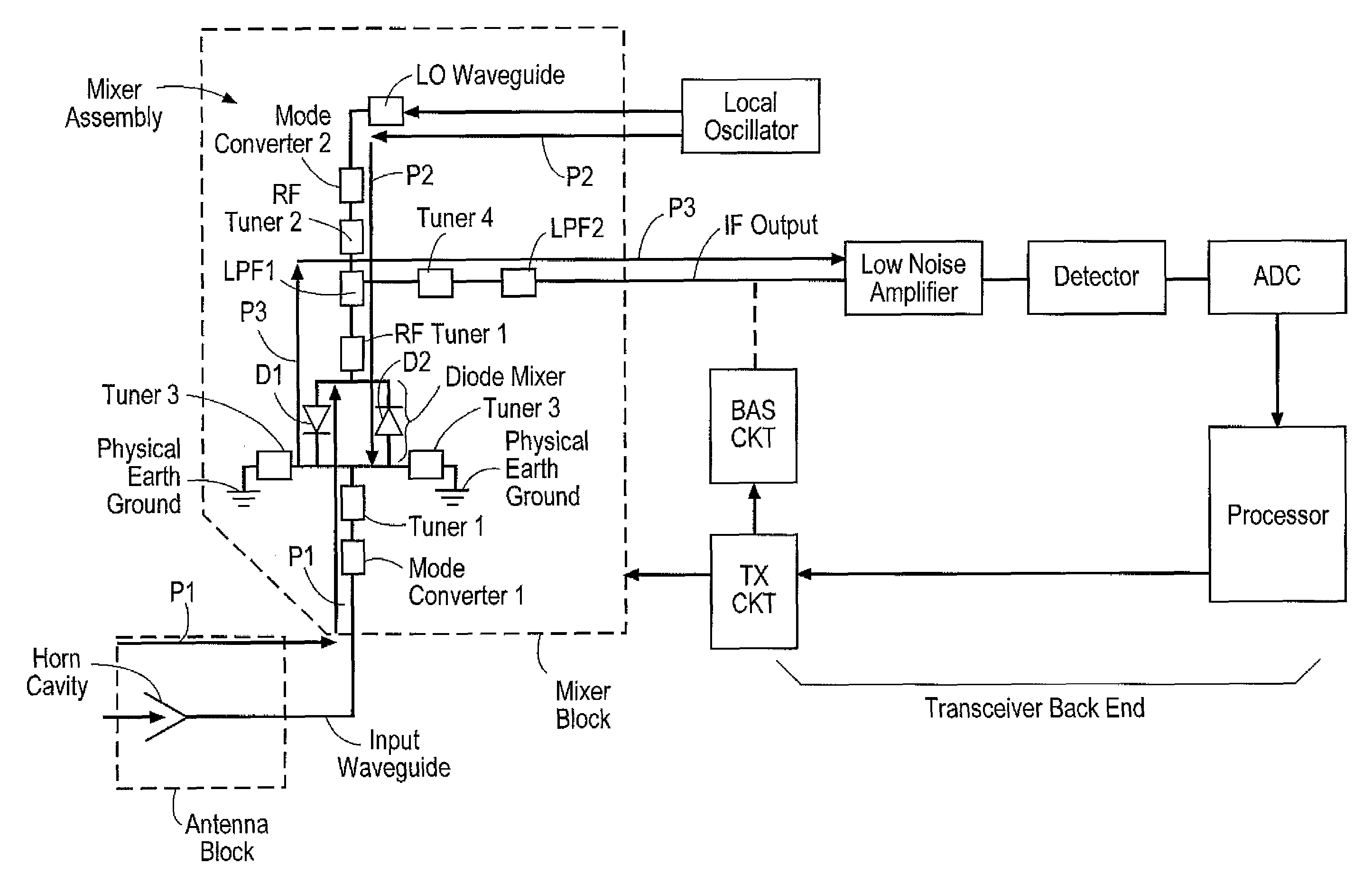
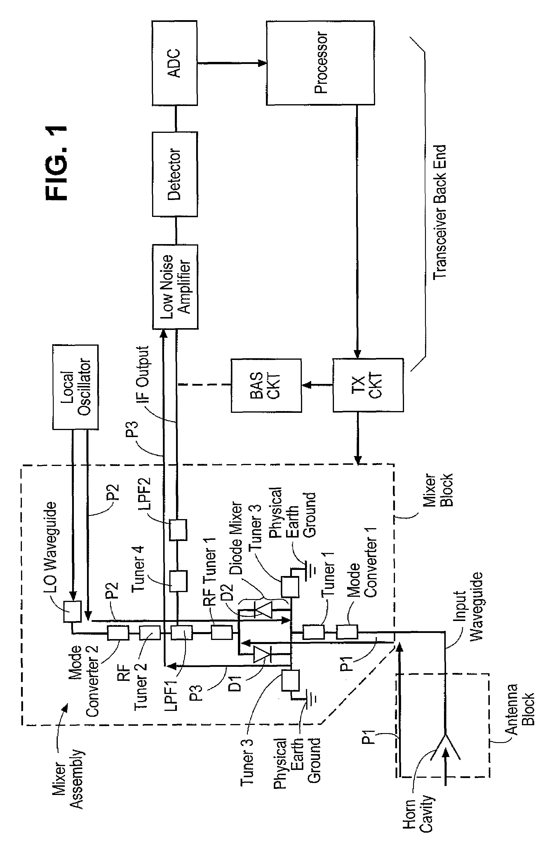
[0040]The present invention provides a transceiver having at least two controllable modes of operation where such transceiver is capable of processing signals of processing signals of different frequency ranges. Examples of types of processing are: receiving signals, transmitting signals, amplifying signals, mixing one signal with another or mixing one group of signals with another group of signals, filtering signals and detecting signals. The present invention encompasses other types of well known processing techniques of signals such A / D conversion and digital signal processing of signals. In general, processing encompasses the manipulation of signals for one or more purposes. A signal's amplitude, frequency, phase and other characteristic can be manipulated when such a signal is being processed. The transceiver of the present invention is capable of processing sub-millimeter signals as well as processing of signals having wavelengths of one millimeter or more. The transceiver of ...


PUM


Abstract

A transceiver capable of processing signals having wavelengths of less than 1 millimeter and / or more than 1 millimeter comprising a mixer / filter circuit coupled to an IF filter where said mixer / filter circuit is positioned within a mixer block to receive incoming signals guided into one or more feed horn openings of the mixer block by an optical arrangement. The IF filter is also disposed within the mixer block, but is positioned substantially orthogonal with respect to the mixer / filter circuit for efficient use of space.

Description

[0001]This application claims the benefit of the filing date of a provisional application having Ser. No. 60 / 794,732 which was filed on Apr. 25, 2006.BACKGROUND OF THE INVENTION[0002]1. Field of the Invention[0003]The present invention relates to a structure and operation for a transceiver device.[0004]2. Description of the Related Art[0005]Electrical and electronic circuitry comprise various types of electrical / electronic components that interact with each other to process signals such as time varying and / or non time varying currents or voltages. The processing of the signals involves the modification of one or more of their characteristics (e.g., signal amplitude, frequency or phase) for a particular purpose. As one or more of the characteristics of the signals change, the physical size and construction of the components needed to process the signals also change; that is, the size of the components used in processing circuitry and the arrangement of the circuitry are directly affe...

Claims


Application Information

Patent Timeline
Patent Type & Authority Applications(United States)
IPC IPC(8): H04B1/38
CPCH01L24/45H01L2224/45144H01L2924/00014H01L2924/01067H01L2924/01019H01L2924/01078H01L2924/01079H01L2924/19041H01L2924/3025H01P3/081H04B1/40H01L2224/48H01L2924/12036H01L2924/00
Inventor MANN, CHRISTOPHER M.GREEN, LESLIE O.COOMBS, DAVID JOHN
Owner THRUVISION LTD
Learn More