Floor slab bridge structure

a bridge structure and floor slab technology, applied in bridge construction, bridge materials, construction, etc., can solve the problems of difficult to ensure, difficult to effectively function, and high execution cost, and achieve the effect of enhancing the strength of the connection concrete, enhancing the strength, and effectively suppressing the expansion and contraction of the bridge girder

Active Publication Date: 2007-11-01
ASAHI ENG CO LTD +1
View PDF3 Cites 7 Cited by
  • Summary
  • Abstract
  • Description
  • Claims
  • Application Information

AI Technical Summary

Benefits of technology

[0013]According to the invention, the connection concrete and the slab concrete cooperate with each other to form a gate type Rahmen structure, it is possible to enhance the strength, with which the bridge girders and the concrete bridge piers are rigidly joined by the connection concrete, to effectively suppress the expansion and contraction, deflection, and distortion of the bridge girders, and to synergistically enhance the strength of the connection concrete itself against the expansion and contraction, distortion, etc., and the structure is very effective as measures for prevention of collapse of bridge against a large earthquake.

Problems solved by technology

However, such flexible joining structure involves a problem that there is a fear of collapse of bridge against a large earthquake and rubber bearings suffer degradation in function due to aged deterioration and are very expensive to increase in execution cost.
However, the method of construction, in which rigid joining is achieved through independent connection concrete additionally deposited every concrete bridge pier, is not functionally effective for strengths for expansion and contraction, distortion, etc. of bridge girders extending long between bridge piers, and difficult to ensure the strength of independent connection concrete itself for expansion and contraction, distortion, etc. of bridge girders, so that the independent connection concrete suffers stress concentration and crack or the like is generated in the bridge girders and the independent connection concrete whereby the structure is difficult to effectively function as earthquake resistant structure against a large earthquake.

Method used


Image

  • Floor slab bridge structure
  • Floor slab bridge structure
  • Floor slab bridge structure

Examples


Embodiment Construction

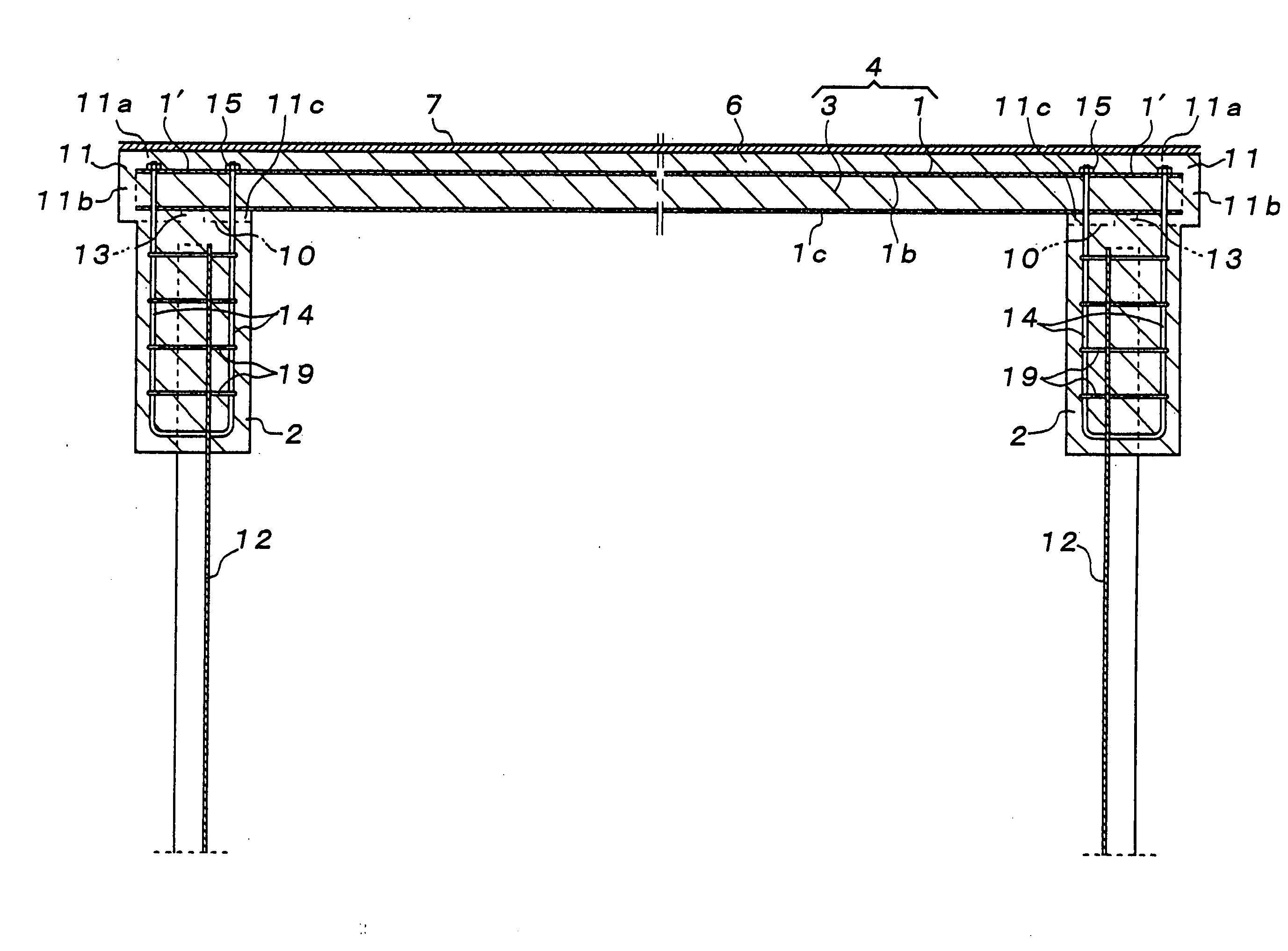
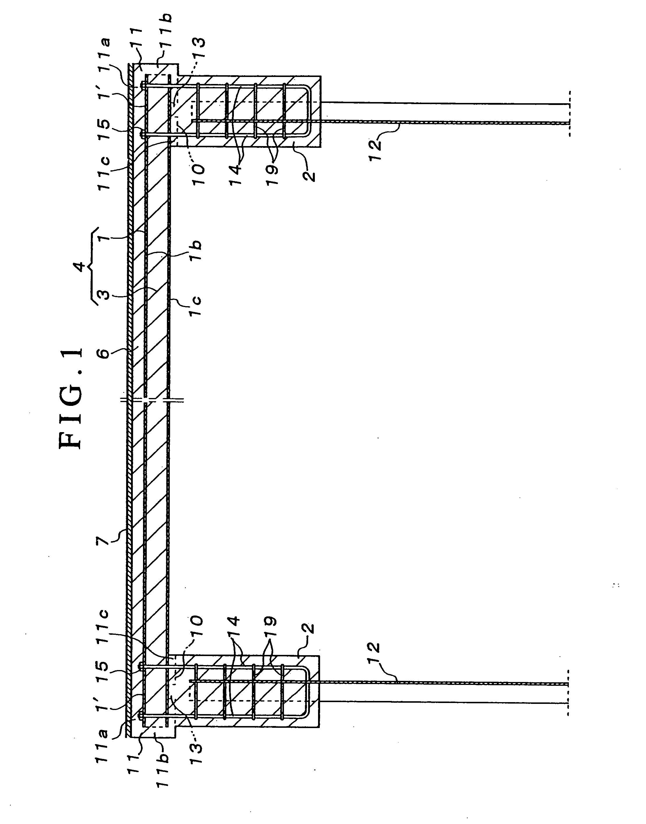
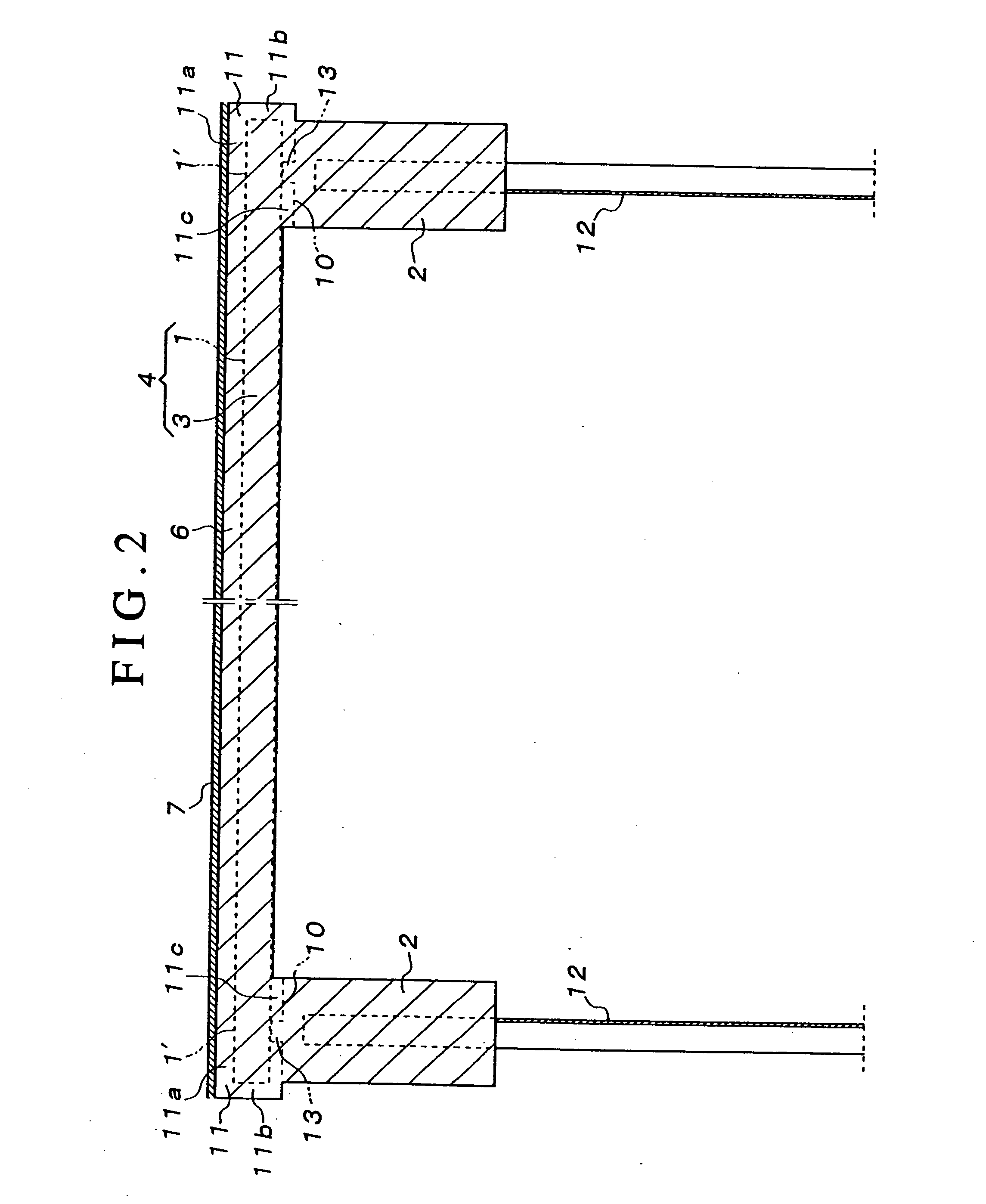
[0023]Embodiments of the invention will be described below with reference to FIGS. 1 to 9.

[0024]As shown in FIGS. 1, 3, 5, and the like, a plurality of bridge girders 1 are supported on bridge piers 2 to be aligned in a bridge width direction and slab concrete 3 is hammer-set and formed between sides of the respective bridge girders 1 in a length direction of the bridge girders 1 whereby a floor slab 4 composed of a composite structure of the bridge girders 1 and the slab concrete 3 is formed.

[0025]FIG. 1 shows a single span floor slab bridge comprising bridge piers 2, which are respectively mounted on opposite banks of a river and on which both ends of bridge girders 1 are supported, and FIG. 3 shows a plural span floor slab bridge comprising bridge piers 2, which support intermediate portions of extensions of the bridge girders 1, the invention being embodied for the single span floor slab bridge and the plural span floor slab bridge.

[0026]The bridge girders 1 comprise a steel gir...


PUM


Abstract

The invention provides a floor slab bridge structure capable of enhancing that strength, with which bridge girders and concrete bridge piers are rigidly joined, effectively suppressing expansion and contraction, deflection, and distortion of the bridge girders, and synergistically enhancing the strength of connection concrete itself against the expansion and contraction, distortion, etc., and being very effective as measures for prevention of collapse of bridge against a large earthquake. Slab concrete is hammer-set between sides of respective bridge girders, which are aligned in a bridge width direction, in a length direction of the bridge girders and connection concrete, in which bridge girder portions supported on bridge bottom surfaces of concrete bridge piers supporting the bridge girders are embedded, is additionally deposited on the bridge bottom surfaces to form a floor slab bridge structure being a rigid joining structure, in which the slab concrete and the concrete bridge piers are concrete-joined together through the connection concrete.

Description

BACKGROUND OF THE INVENTION[0001]1. Field of the Invention[0002]The present invention relates to a floor slab bridge structure formed by hammer-setting slab concrete between sides of respective bridge girders, which are aligned in a bridge width direction, in a length direction of the bridge girders and comprising a composite structure of the bridge girders and the slab concrete.[0003]2. Description of Related Art[0004]Conventional floor slab bridges adopt a flexible joining structure, in which bridge girders are supported on bridge bottom surfaces of concrete bridge piers through rubber bearings and expansion and contraction, deflection, or distortion of the bridge girders are absorbed by the rubber bearings.[0005]However, such flexible joining structure involves a problem that there is a fear of collapse of bridge against a large earthquake and rubber bearings suffer degradation in function due to aged deterioration and are very expensive to increase in execution cost.[0006]On the...

Claims


Application Information

Patent Timeline
Patent Type & Authority Applications(United States)
IPC IPC(8): E01D19/02
CPCE01D2/00E02D27/30E01D2101/268E01D2101/26E01D19/12
Inventor TOKUNO, MITSUHIROSAITO, FUMIHIRO
Owner ASAHI ENG CO LTD
Why Eureka
Try Eureka