Cyclonic Plasma Pyrolysis/Vitrification System

a plasma pyrolysis and plasma technology, applied in the field of plasma pyrolysis/vitrification system, can solve the problems of reducing the volume of flyashes, generating harmful exhaust gases, and reducing the volume of landfills,

Inactive Publication Date: 2007-11-01
ADPLATECH
View PDF7 Cites 6 Cited by
  • Summary
  • Abstract
  • Description
  • Claims
  • Application Information

AI Technical Summary

Benefits of technology

[0008] The advantage of plasma treatment that volume of landfill is decreased may be offset when the volume of the flyashes is large, because the flyashes discharged to the outside should be either re-treated after collecting in a gas purification equipment or landfilled.

Problems solved by technology

However, the landfill may not be a perfect solution due to shortage of landfill sites, and contamination of underground water and soil.
However, they have a disadvantage of generating harmful exhaust gases such as dioxin, and residual ashes containing heavy metals.

Method used


Image

  • Cyclonic Plasma Pyrolysis/Vitrification System
  • Cyclonic Plasma Pyrolysis/Vitrification System
  • Cyclonic Plasma Pyrolysis/Vitrification System

Examples


example 2

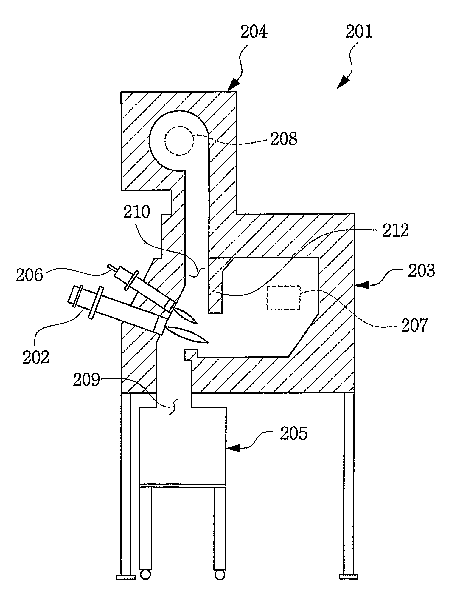
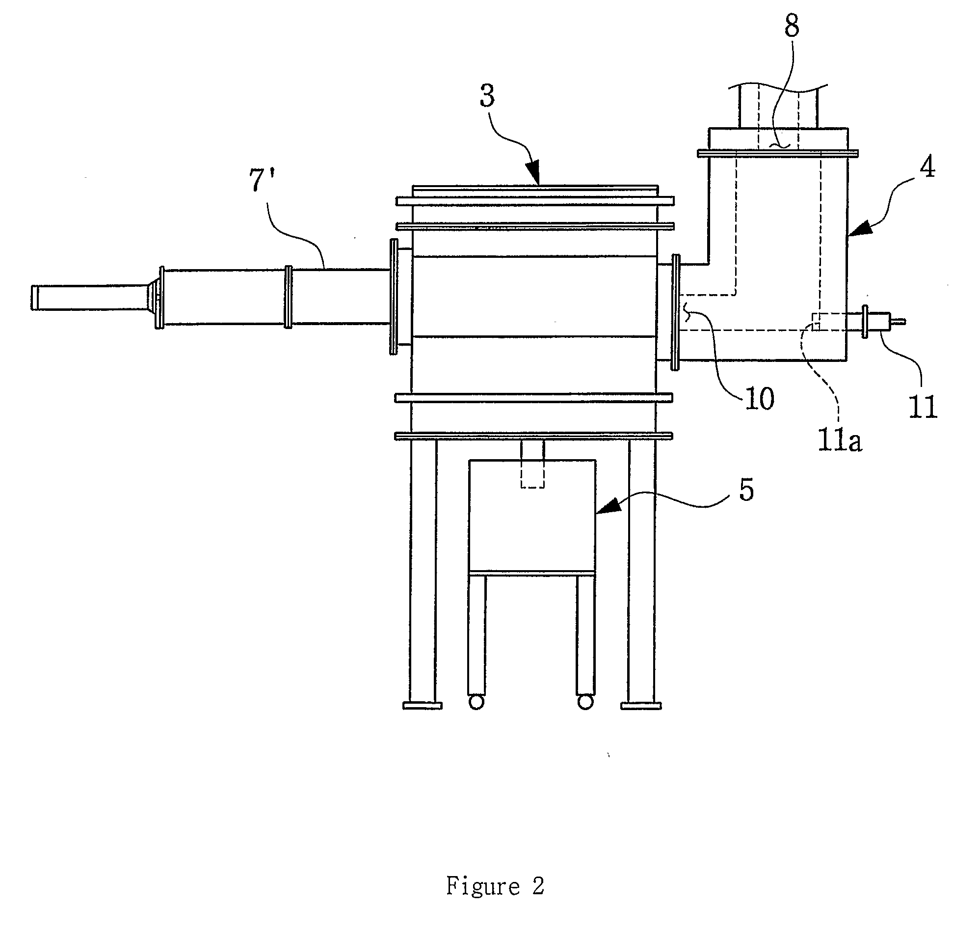
[0029]FIG. 3 is a partial sectional view showing a cyclonic plasma pyrolysis / vitrification system in accordance with Example 2 of the present invention and FIG. 4 is a partial side view showing the cyclonic plasma pyrolysis / vitrification system in accordance with Example 2 of the present invention.

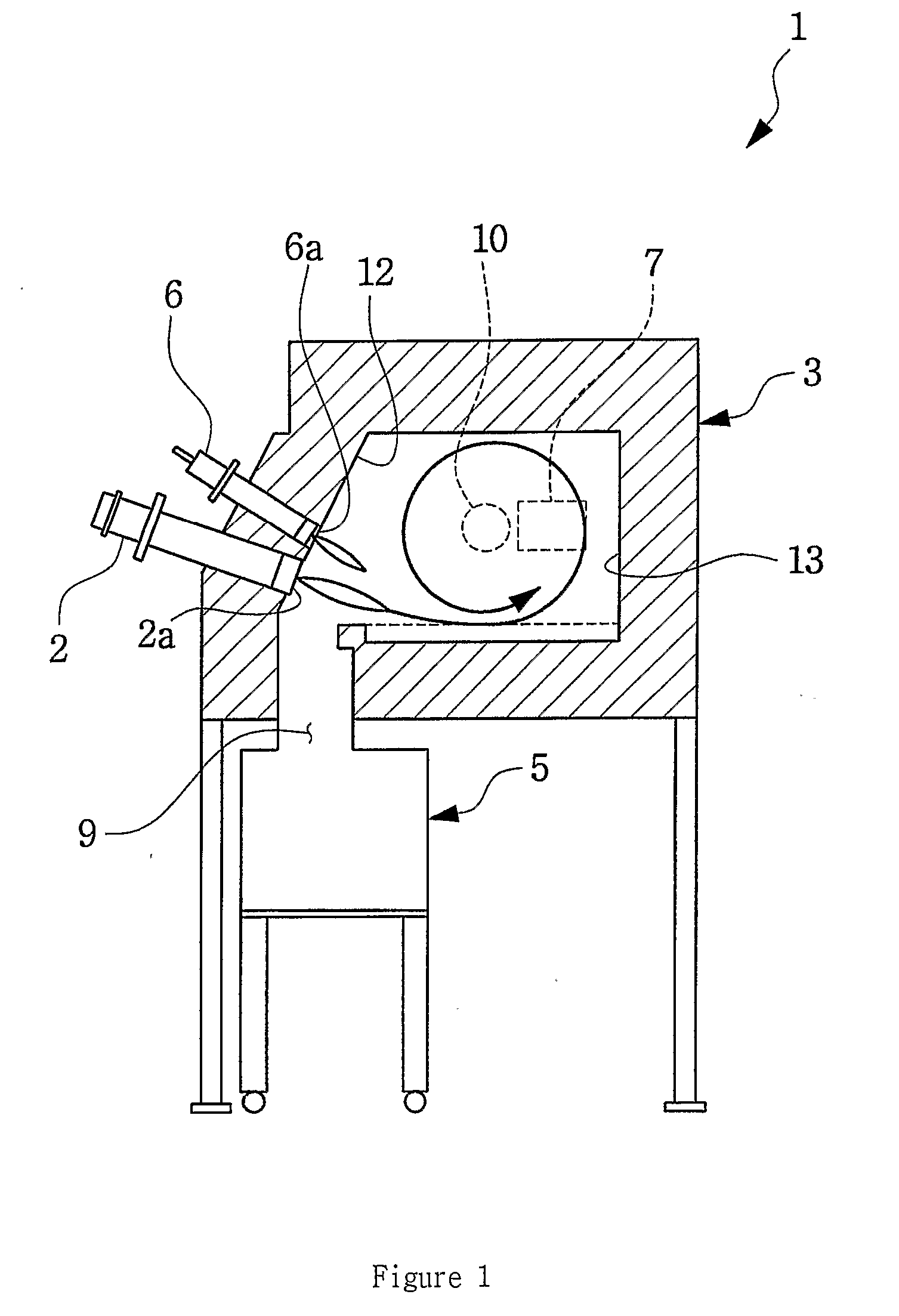
[0030] Referring to FIGS. 3 and 4, a cyclonic plasma pyrolysis / vitrification system 201 is an equipment for pyrolyzing and vitrifying waste materials, in the same manner as Example 1 shown in FIG. 1. The cyclonic plasma pyrolysis / vitrification system 201 comprises a plasma torch 202 pyrolyzing and vitrifying waste materials, a main reactor 203 generating exhaust gas and slag by pyrolyzing and vitrifying the waste materials using the plasma torch 202, an auxiliary reactor 204 to which the exhaust gas generated in the main reactor 203 is fed and which discharges the exhaust gas to the outside, and a slag discharger 205 to which the slag generated in the main reactor 203 is fed and which dis...


PUM


Abstract

The present invention relates to a cyclonic plasma pyrolysis/vitrification system pyrolyzing and vitrifying waste materials into exhaust gas and slag using a plasma torch. The plasma torch circulates the exhaust gas in a main reactor with a maximum circulating power by strong plasma jet, and makes flyashes contained in the circulating exhaust gas to be melted after being adsorbed at the inner walls or in the melted materials of waste at the bottom of the main reactor by a centrifugal force. Accordingly, discharge of flyashes containing toxic materials to the outside is prevented, and pyrolysis and gasification of the waste materials are induced by circulating the exhaust gas rapidly.

Description

TECHNICAL FIELD [0001] The present invention relates generally to a pyrolysis / vitrification system for treating waste materials and, more particularly, to a plasma pyrolysis / vitrification system utilizing plasma with low mass, ultra high temperature and high enthalpy to transform organic waste materials into fuel gas by pyrolysis and gasification, and inorganic waste materials into harmless recyclable slag by melting simultaneously. BACKGROUND ART [0002] Recently the amount of industrial / household waste materials is increasing rapidly due to fast industrialization and population growth. Landfill is generally used for treating the waste materials. However, the landfill may not be a perfect solution due to shortage of landfill sites, and contamination of underground water and soil. Based on incineration, various new technologies having advantages such as volume reduction and energy recycling have been developed, and are being used currently. However, they have a disadvantage of genera...

Claims


Application Information

Patent Timeline
Patent Type & Authority Applications(United States)
IPC IPC(8): F23G5/00F23G5/027F23G5/08F23G5/32
CPCF23G5/0276F23G5/085F23G2204/201F23G2202/104F23G2202/20F23G5/32F23G5/00
Inventor HWANG, SOON MOKIM, YOUNG SUKDOH, CHEAL JIN
Owner ADPLATECH
Why Eureka
Try Eureka