
Satellite active motion damping

a technology of active motion and satellite, applied in the direction of vehicle position/course/altitude control, process and machine control, instruments, etc., can solve the problems of affecting the safety of satellite attitude control system operation, and affecting the stability of satellites. , to achieve the effect of safe operation of satellite attitude control system

Inactive Publication Date: 2007-11-01
HONEYWELL INT INC
View PDF6 Cites 15 Cited by
  • Summary
  • Abstract
  • Description
  • Claims
  • Application Information

AI Technical Summary

Benefits of technology

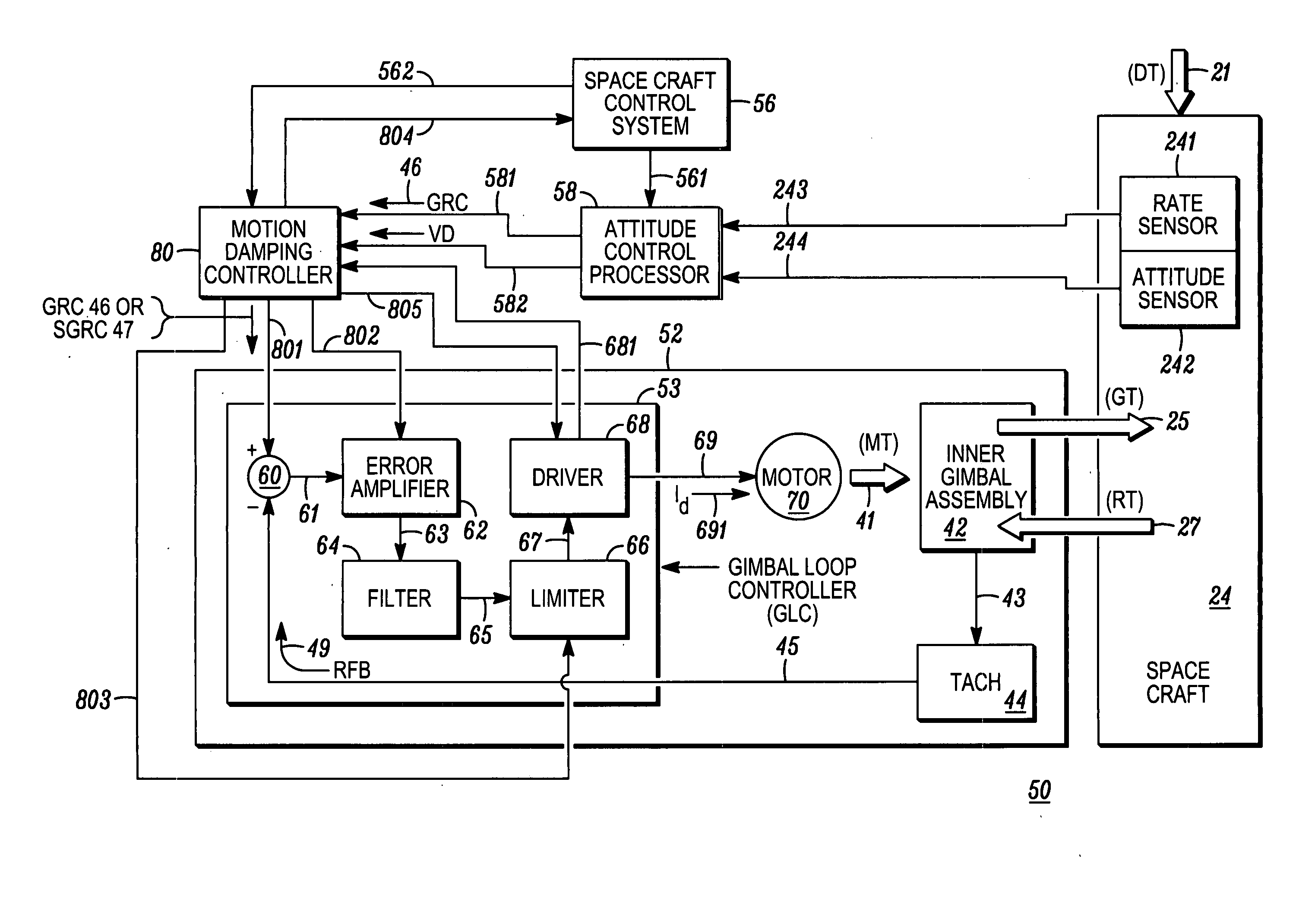
[0008] A method is provided for safely operating a satellite attitude control system employing at least one control moment gyro (CMG) responsive to attitude change commands. The method comprises, receiving an attitude change command, determining whether the received attitude change command is valid, and if YES (TRUE), having the CMG execute the valid attitude change command, and if NO (FALSE), modifying operation of the CMG to enable active motion damping (AMD) wherein rotation of the satellite is gradually changed to a quiescent state without exceeding a predetermined safe rate of change of rotation.

Problems solved by technology

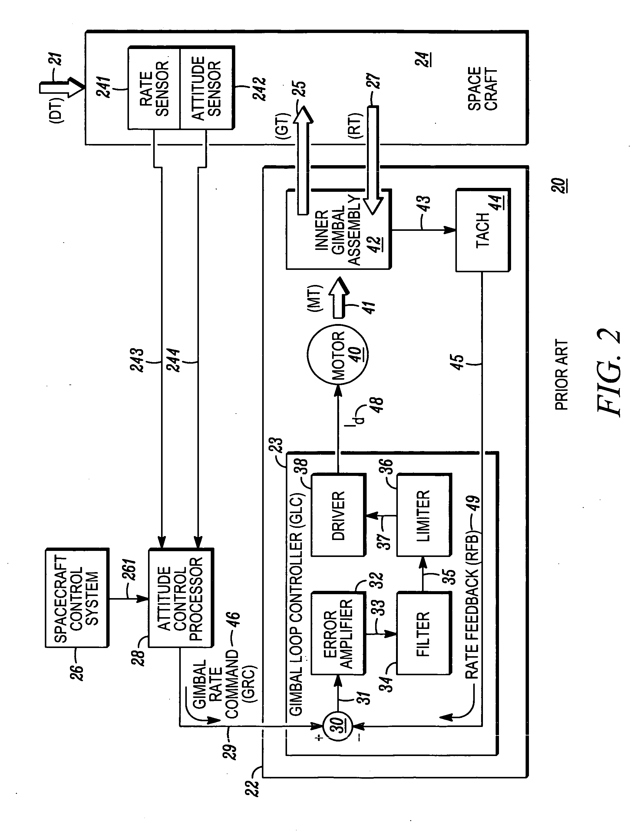
A problem with such systems is that if a spacecraft is moving as a result of prior gimbal rate command (GRC) 46 having been issued to CMG 22 from ACP 28, and ACP 28 or some other element of the system has a malfunction or reaches a time-out so that gimbal rate command (GRC) 46 being issued by ACP 28 drops to zero or otherwise becomes invalid, then spacecraft 24 and CMG 22 can be subjected to very severe mechanical stresses.
This can result in a sudden and potentially harmful deceleration of inner gimbal assembly 42 and spacecraft 24.
This process can also result in damaging stresses to the CMG system and the spacecraft structure.
But some spacecraft employ non-geared, direct drive gimbal motors, where this approach is not practical.
Hence, the problem is exacerbated with these vehicles.

Method used


Image

  • Satellite active motion damping
  • Satellite active motion damping
  • Satellite active motion damping

Examples


Embodiment Construction

[0015] The following detailed description is merely exemplary in nature and is not intended to limit the invention or the application and uses of the invention. Furthermore, there is no intention to be bound by any expressed or implied theory presented in the preceding technical field, background, brief summary or the following detailed description.

[0016] For simplicity and clarity of illustration, the drawing figures illustrate the general manner of construction and method of operation, and descriptions and details of well-known features and techniques may be omitted to avoid unnecessarily obscuring the invention. Additionally, elements in the drawings figures are not necessarily drawn to scale. For example, the dimensions of some of the elements or regions in the figures may be exaggerated relative to other elements or regions to help improve understanding of embodiments of the invention

[0017] The terms “first,”“second,”“third,”“fourth” and the like in the description and the cl...


PUM


Abstract

Methods and apparatus are provided for active motion damping of a spacecraft whose attitude control system (SACS) has experienced a partial failure. In a preferred embodiment, the apparatus comprises, an attitude control processor (ACP), a motion damping controller (MDC) coupled to the ACP, a control moment gyro (CMG) comprising a gimbal loop controller (GLC) coupled to the MDC and a gimbal motor with input coupled to the GLC and gyroscopic torque output coupled to the satellite. Normally, a gimbal rate command (GRC) from the ACP passes to the GLC for execution to rotate the CMG gimbal and the coupled satellite. If the ACP output becomes invalid, the MDC assumes control and can modify CMG operation in several ways to safely decelerate a moving satellite without hazardous mechanical stress. Following such active motion damping, the CMG remains quiescent until a RESET is received whereby further valid GRCs are then executable.

Description

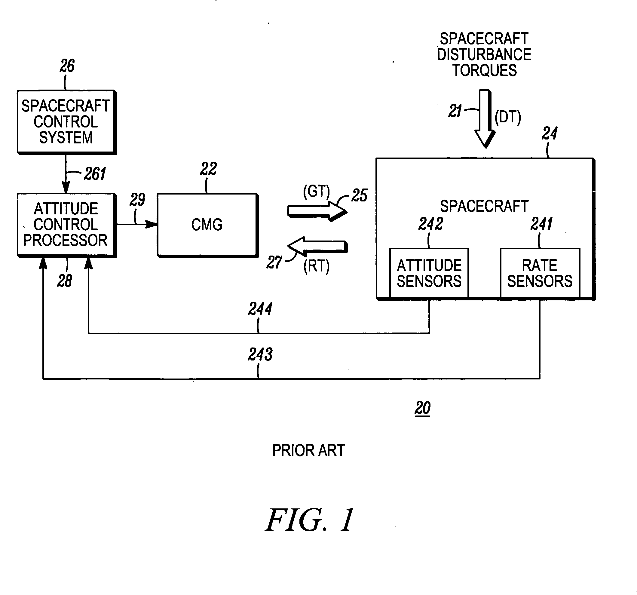
TECHNICAL FIELD [0001] The present invention generally relates to attitude control systems for satellites and other space vehicles, and more particularly relates to active motion damping of such systems. BACKGROUND [0002] Control moment gyros (CMG's) are widely used in attitude control systems of satellites and other space vehicles. The words “spacecraft”, “satellite” and “space vehicle” are used synonymously herein. Persons of skill in the art understand that multiple CMG's are often used to permit orientation control in three dimensions. However, for convenience of explanation, it is assumed herein that the orientation system is one dimensional, i.e., employing only one CMG. Persons of skill in the art will understand that multiple CMG's can be employed to provide for orientation in three dimensions and that the present invention applies to such multidimensional arrangements. [0003]FIG. 1 is a simplified schematic block diagram illustrating conventional prior art spacecraft attitu...

Claims


Application Information

Patent Timeline
Patent Type & Authority Applications(United States)
IPC IPC(8): B64G1/28
CPCB64G1/286G05D1/0883B64G1/38B64G1/244
Inventor JACKSON, LOUIS R.ROGERS, BRUCE W.WINKEL, ROBERT E.
Owner HONEYWELL INT INC
Learn More