Method for making multi-layer preform

a multi-layer, plastic preform technology, applied in the direction of layered products, chemistry apparatus and processes, other domestic articles, etc., can solve the problems of limited multi-layer capability, high cost of machine and mold costs, and greatly reduced process quality when employed, so as to reduce cooling time, increase production, and speed up cycle time

Inactive Publication Date: 2007-11-01
GRAHAM PACKAGING CO LP
View PDF5 Cites 14 Cited by
  • Summary
  • Abstract
  • Description
  • Claims
  • Application Information

AI Technical Summary

Benefits of technology

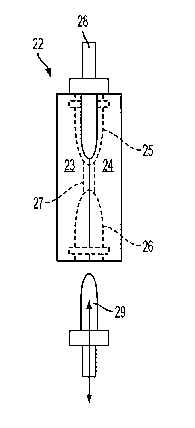
[0015] Another advantage of the present invention compared to known blow molding processes is that the preform can be made with decreased cooling times. This is because the compression preform core is cooled via water being circulated there through. Thus, the plastic of the formed preform can be cooled both on the inside (core-side) and the outside (mold-side) due to the insertion of the preform core. This results in faster cycle times thereby increasing production.
[0016] Further objectives and advantages, as well as the structure and function of preferred embodiments will become apparent from a consideration of the description, drawings, and examples.

Problems solved by technology

Although this manufacturing technique is satisfactory for fabrication of mono-layer plastic containers, the throughput quality of the process is greatly reduced when employed for fabricating multi-layer, plastic preforms and containers.
For example, a preform formed by compression or injection molding involves expensive machine and mold costs due to the complex molds with moving parts that are required to form threads of the finish.
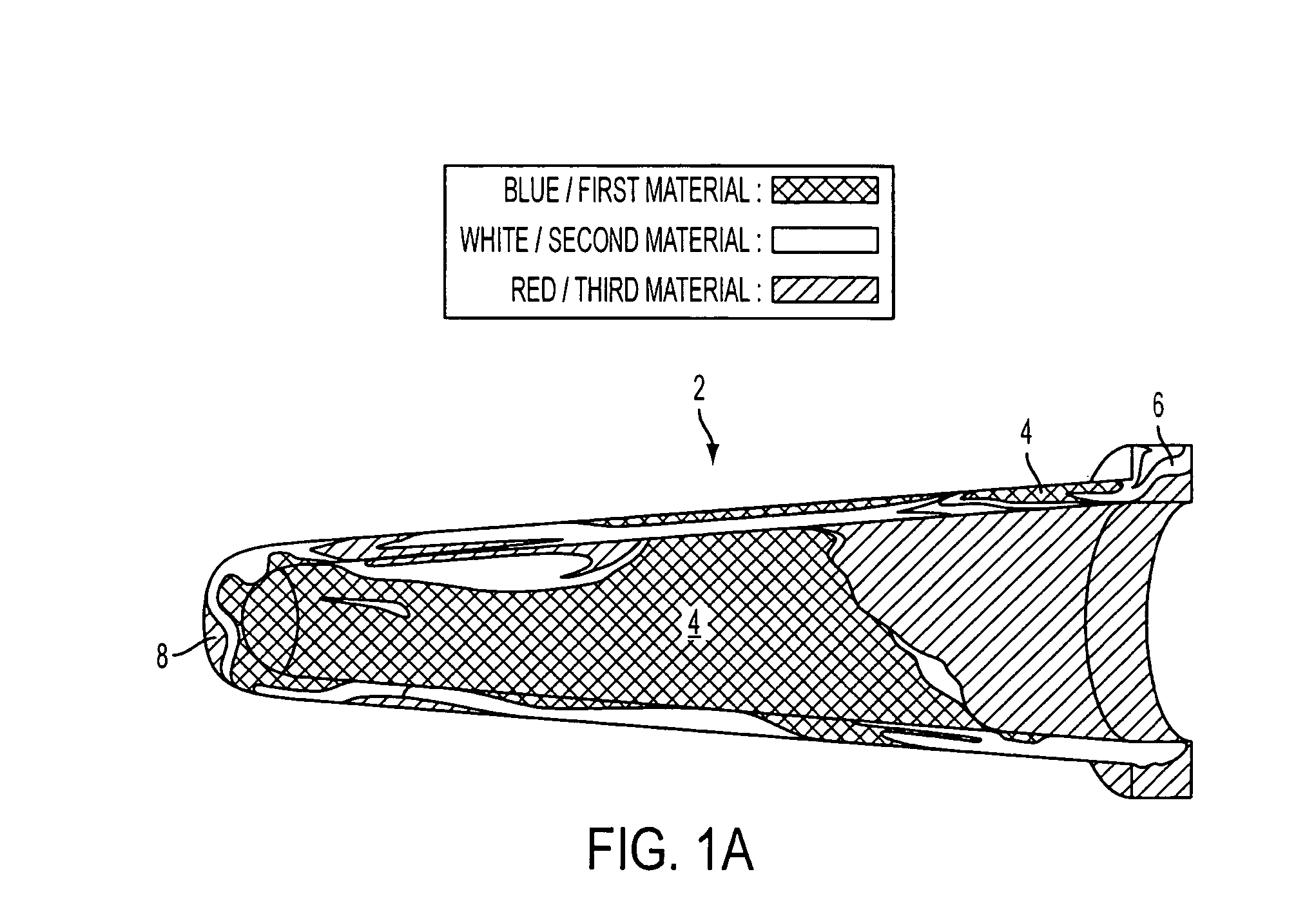
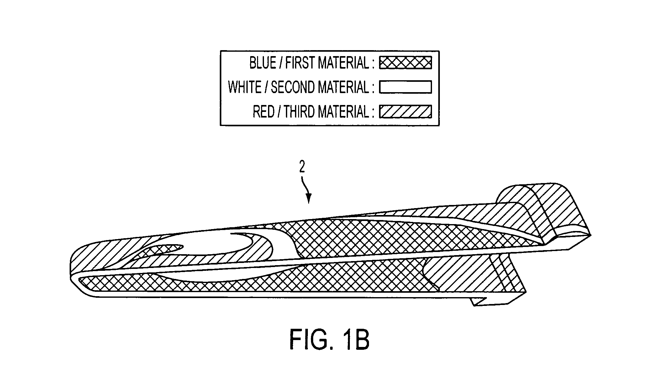
In addition, multi-layer capability is limited with compression molding as the multi-layer plastic smears disrupting the orientation of the layers as the preform parison is compressed against the plastic.
However, performs formed by air-blowing tubular parisons are problematic as the distribution of the preform wall thickness is inconsistent.
However, preforms formed by air-blowing tubular parisons are problematic as the distribution of the preform wall thickness is inconsistent.
In addition to the rupturing problem, blow molding may form areas that are too thick resulting in cooling problems of the resultant container and / or a container that is not pleasing to the eye.

Method used


Image

  • Method for making multi-layer preform
  • Method for making multi-layer preform
  • Method for making multi-layer preform

Examples


Embodiment Construction

[0030] Embodiments of the invention are discussed in detail below. In describing embodiments, specific terminology is employed for the sake of clarity. However, the invention is not intended to be limited to the specific terminology so selected. While specific exemplary embodiments are discussed, it should be understood that this is done for illustration purposes only. A person skilled in the relevant art will recognize that other components and configurations can be used without parting from the spirit and scope of the invention.

[0031] Looking at FIG. 3, a shuttling operation for making a multi-layer plastic preform is shown that moves from the left side of the page to the right side of the page. At the first shuttle step 10, a multi-layer parison 12 is generated above a preform mold 14 with a preform cavity 15. The generated multi-layer parison may have two (2), three (3), or four (4) to six (6) layers of material. In certain applications, more than six layers of material may be ...


PUM

PropertyMeasurementUnit
thicknessaaaaaaaaaa
critical temperatureaaaaaaaaaa
pressureaaaaaaaaaa

Abstract

A method for making a multi-layer plastic preform employs blow molding air into the multi-layer parison until an outer layer of the multi-layer parison rests against the preform mold and thereafter inserting a compression core sized to fit the pre-blown preform to smooth the inner layer of the blown parison and finish the preform. A system for making a multi-layer plastic preform includes a blow stem assembly having a device for introducing air into a multi-layer parison captured by a preform mold in a blow-mold operation, and a compression preform core attached to an end of a compression rod wherein when the compression preform core is retracted into the device, air can be blown into the preform mold and when, the compression rod extends in a stroke through the device, the compression preform core extends out of the device into the preform mold.

Description

BACKGROUND OF THE INVENTION [0001] 1. Field of the Invention [0002] The present invention relates generally to an apparatus and method for making a multi-layer, plastic preform that can be utilized in the stretch-blow molding process. More particularly, the invention relates to such a method and apparatus that utilizes standard machine equipment to produce a compression quality multi- or mono-layer, plastic preform. [0003] 2. Related Art [0004] In the manufacture of plastic containers, such as monolayer or multilayer PET containers, it is conventional to mold a container preform having a body and a finish with one or more external threads. The finish is typically molded to its final geometry, while the body of the preform is subsequently blow molded to the desired geometry of the container body. Although this manufacturing technique is satisfactory for fabrication of mono-layer plastic containers, the throughput quality of the process is greatly reduced when employed for fabricating...

Claims


Application Information

Patent Timeline
Patent Type & Authority Applications(United States)
IPC IPC(8): B29C49/22B29C49/02B29C49/18
CPCB29B11/10B29L2031/7158B29B2911/1402B29B2911/14026B29B2911/14033B29B2911/1404B29B2911/14053B29B2911/14066B29B2911/1408B29B2911/14093B29B2911/14106B29B2911/14113B29B2911/1412B29B2911/14126B29B2911/14166B29B2911/14173B29B2911/1418B29B2911/1422B29B2911/14226B29B2911/14233B29B2911/14313B29B2911/14326B29B2911/14333B29B2911/14366B29B2911/14593B29B2911/14646B29B2911/14986B29B2911/14993B29C43/00B29C43/14B29C43/203B29C43/36B29C49/0073B29C49/04B29C49/18B29K2023/086B29K2023/12B29K2105/258B29K2105/26B29K2623/12B29B11/12B29C2949/3008B29C2949/3012B29C2949/3026B29C2949/302B29C2949/3016B29C2949/303B29C2949/3024B29C2949/3028B29C2949/26B29C2949/28B29C2949/24B29C2949/3044B29C2949/22B29C2949/3046B29C2949/3058B29C2949/3042B29C2949/3062B29C2949/306B29C2949/3092B29C2949/0762B29C2949/0733B29C2949/073B29C2949/0819B29C2949/072B29C2949/0811B29C49/0005B29C49/071
Inventor PENNINGTON, GARRETTO'CONNELL, PATTAYLOR, GREGORY
Owner GRAHAM PACKAGING CO LP
Why Eureka
Try Eureka