
Method and system for illuminating an indicator

Inactive Publication Date: 2007-11-01
DELPHI TECH INC
View PDF11 Cites 7 Cited by
  • Summary
  • Abstract
  • Description
  • Claims
  • Application Information

AI Technical Summary

Benefits of technology

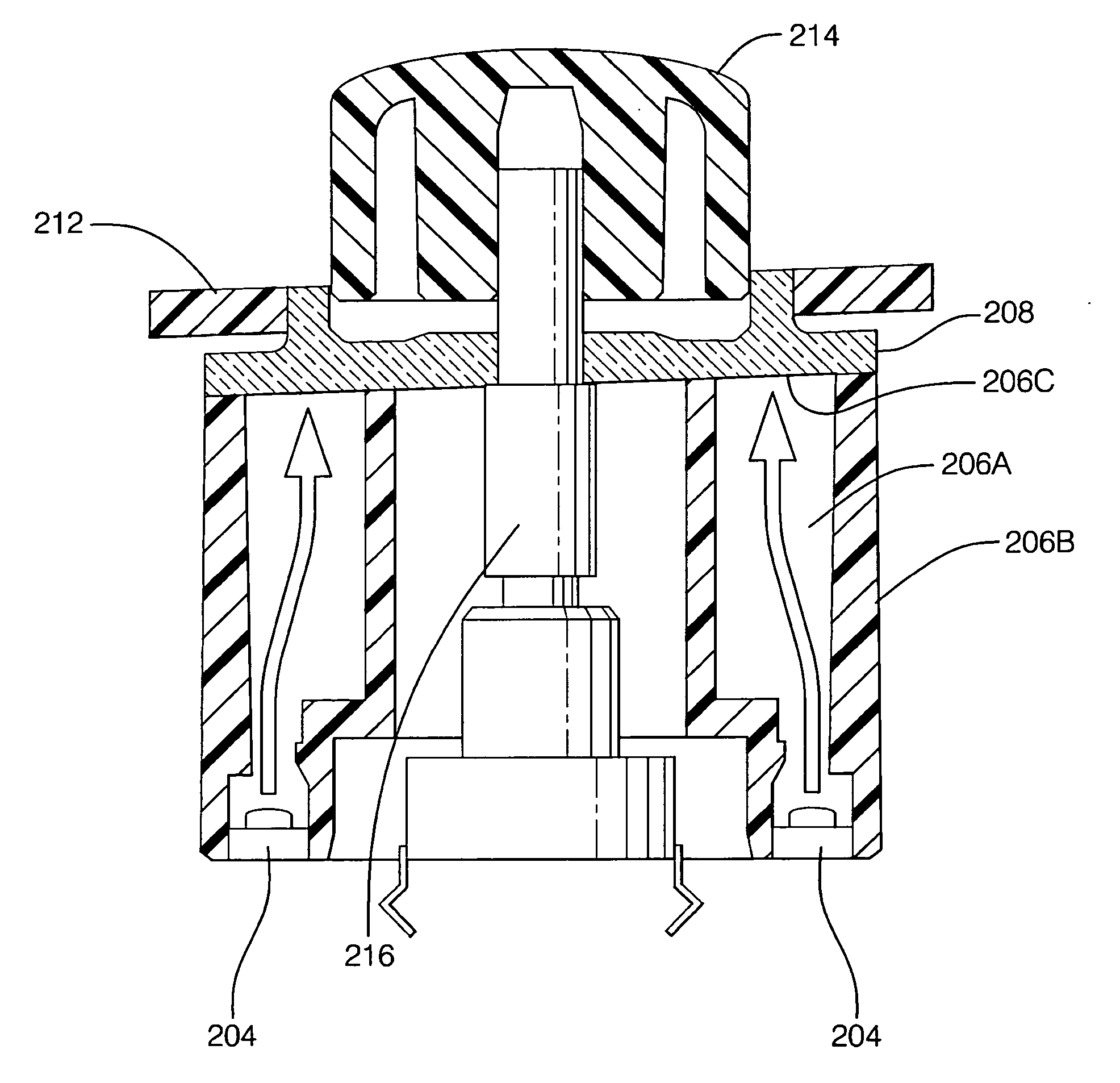
[0006] A method and system are provided to illuminate an indicator. The present invention is useful to and can improve a wide range of illuminated indicators including motor vehicle controls visible to an operator, and indicators for other electronic systems and appliances. The indicators may be formed with varied shapes including a lighted ring, or straight bar. Systems having decorative graphics may utilize the present invention as well.
[0007] Improved visual appearance of a lighted indicator is provided, which may be especially appreciated when the lighting is apparent such as at night. Light is evenly distributed to an indicator using a minimum number of components. Lighting efficiency is maximized. Light leaks, shadows, internal reflections, color bleeds, and other undesirable visual effects are avoided. Further, the surface of the indicator that receives light is increased as compared to contemporary devices. This further improves light distribution, avoids undesirable visual effects, and allows for an increased fit tolerance between the light source and the indicator.
[0008] The present invention also provides a tight tolerance between an indicator and a control knob. Thus, in addition to avoiding leaks and shadows by minimizing gaps, typical secondary operations and components needed to block light leaks, bright spots, and internal reflections are eliminated. Production and assembly costs are reduced as compared to conventional devices since, in an embodiment, part numbers are reduced and the system may be integrated with standard components.
[0011] In an embodiment, the indicator is shaped with a maximized base area adjacent to the lightbox to create a large pad printing area and to increase fit tolerance of the lightbox to the indicator. The indicator can be formed as a color display such that a color represents a particular system setting. The indicator may be shaped in numerous forms including a halo ring or a form having a straight perimeter. Additionally, the indicator can be utilized to align the positioning of the encoder. A knob may be affixed to the encoder to facilitate grasping the encoder. A faceplate can be positioned between the indicator and the knob. Further, the present invention reduces the number of components to illuminate an indicator by, for example, integrating the lightbox as part of a switchpad.

Problems solved by technology

An improved appearance of an illuminated indicator is needed however, since contemporary indicators are often unevenly lit and plagued by light leaks and other undesirable visual effects.
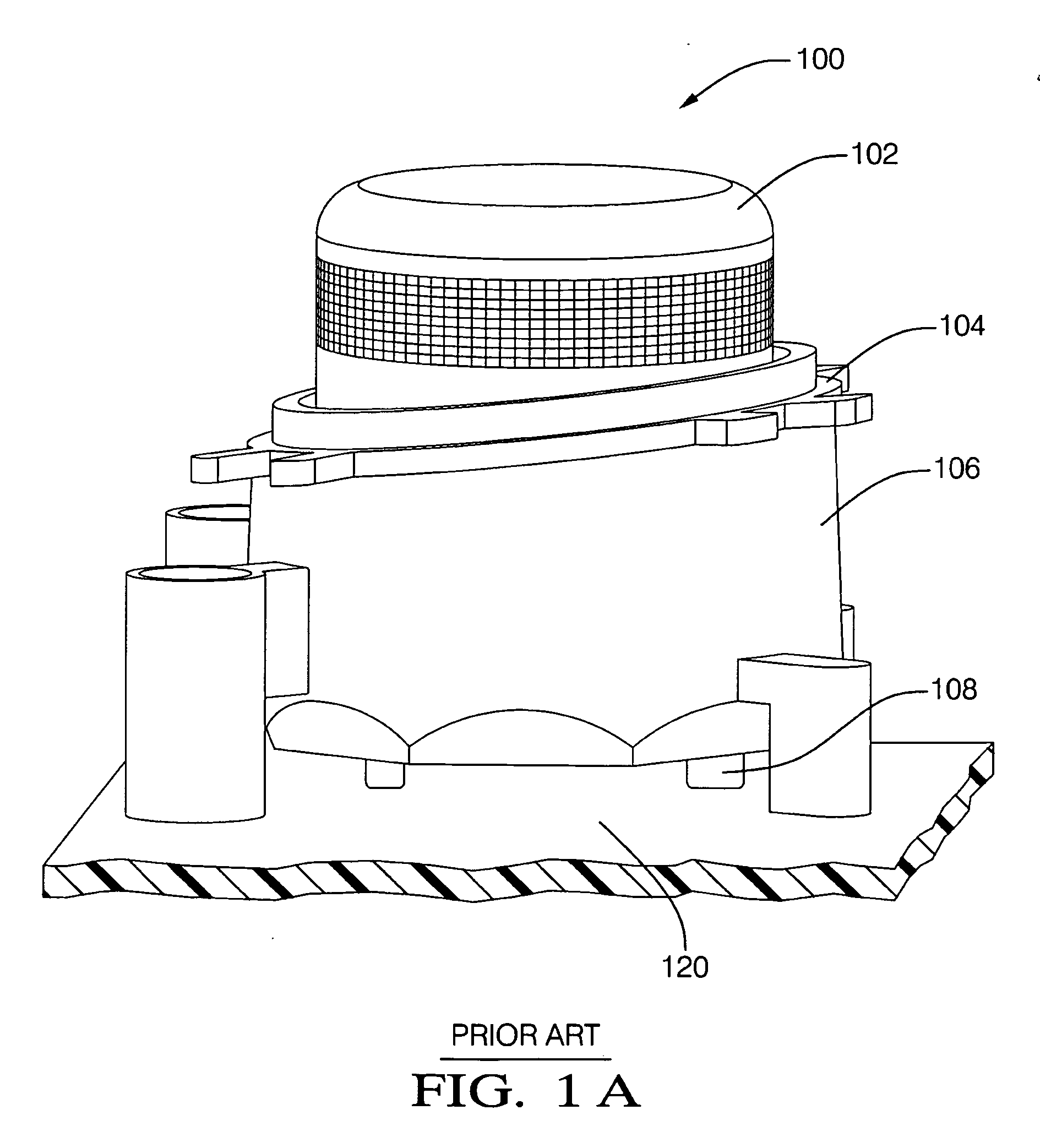
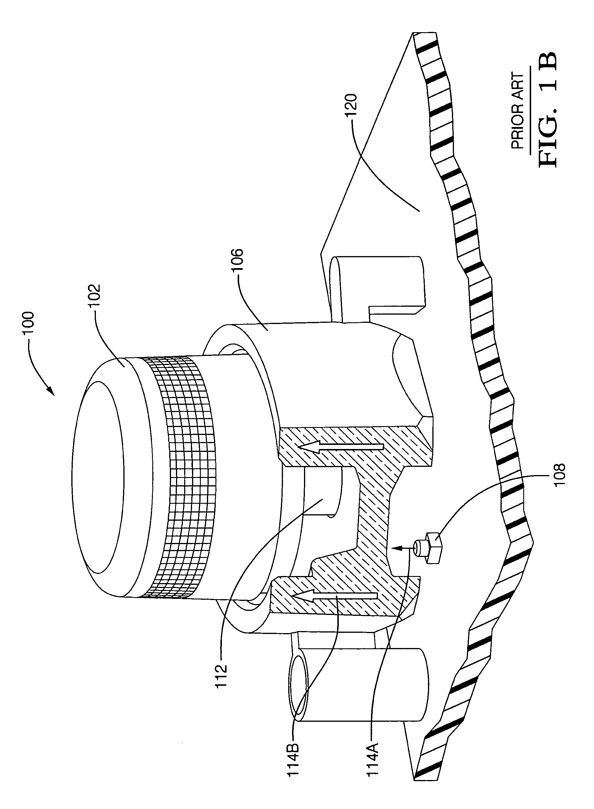
This lightpipe design includes a number of individual components such that gaps are difficult to control and are therefore created between the components.
These gaps cause unwanted visual effects including shadows and light leaks, especially between the indicator and control knob, which is visible to a vehicle operator.
Still, the lightpipe and the indicator usually experience mixed colors and unwanted visual effects including light leaks, reflections, black rings, and dim lighting.
The addition of a bezel increases the number of system components and the design cost.
While the gaps are less than the previously mentioned lightpipe design, undesirable visual effects are still present.
Moreover, the fit of the halo ring to the lightpipe is critical and must be exact or light intended to be transmitted to the halo ring indicator is lost and visible internal reflections and light leaks occur.
Further, the centering of the encoder is dependent on the tolerances of the halo, lightpipe and faceplate, which increases centering error.
Again, undesirable visual effects are present including uneven lighting, shadows, reflections, light leaks and bleeding indicator colors.

Method used


Image

  • Method and system for illuminating an indicator
  • Method and system for illuminating an indicator
  • Method and system for illuminating an indicator

Examples


Embodiment Construction

[0022] Exemplary embodiments are described with reference to specific configurations. Those of ordinary skill in the art will appreciate that various changes and modifications can be made while remaining within the scope of the appended claims. Additionally, well-known elements, devices, components, methods, process steps and the like may not be set forth in detail in order to avoid obscuring the invention. Further, unless indicated to the contrary, any numerical values set forth in the following specification and claims are approximations that may vary depending upon the desired characteristics sought to be obtained by the present invention.

[0023] A system and method is described herein for illuminating an indicator. The present invention provides improved visual appearance of a lighted indicator, which can be especially appreciated when artificial lighting is apparent in dark environments and at night. Light is uniformly distributed to an indicator using a minimum number of compo...


PUM


Abstract

A method and system are provided to illuminate an indicator, including indicators for electronic systems, appliances, and motor vehicle settings such as a visible temperature setting. Lighting efficiency is maximized, while light leaks, bright spots, shadows, internal reflections, color bleeds, and other undesirable visual effects are avoided. A lightbox having a cavity contains emitted light and transmits the light to an indicator. The indicator displays a system setting and an encoder varies the system setting. In an aspect, a light block and ramp are formed in the lightbox to uniformly dispense light to the indicator. A light dividing ridge formed in the lightbox separates the light dispensed to separate sections of the indicator. Further improvements include a tight fit formed between the indicator and a control knob, and a maximized indicator base area adjacent to the lightbox. The lightbox can also be integrated as part of a switchpad, reducing costs.

Description

FIELD OF THE INVENTION [0001] The invention relates generally to illuminating an indicator, and more particularly to uniformly distributing light to an indicator, and avoiding light leaks, shadows, reflections, color bleeds and other undesirable visual effects. BACKGROUND OF THE INVENTION [0002] Illuminated indicators are utilized for a variety of systems ranging from electronic systems, appliances, and system controls visible to an operator of a motor vehicle to decorative graphics. Numerous systems incorporate a lighted halo ring, straight bar or graphics. In regard to system controls visible to an operator of a motor vehicle, halo rings are often used around knobs to provide information to the vehicle operator. When the knob controls the climate of the vehicle passenger compartment, generally the temperature is adjusted by means of a color code. Red characteristically indicates a warmer temperature while blue indicates a cooler temperature. When nighttime brings darkness to the p...

Claims


Application Information

Patent Timeline
IPC IPC(8): G09F13/04
CPCG01D11/28
Inventor PALACIO, ANIBAL
Owner DELPHI TECH INC
Learn More