Image forming apparatus, lubricant applying apparatus, control method of image forming apparatus

a technology of lubricant and image forming apparatus, which is applied in the direction of electrographic process apparatus, instruments, and corona discharge, etc., can solve the problems of tarnishing the lubricant supply brush, difficult to uniformly apply the lubricant to the surface of the image carrier in a stable manner for an extended period of time, and affecting the stability of the image carrier, so as to achieve the effect of less consumption of lubrican

Inactive Publication Date: 2007-11-01
SHARP KK
View PDF8 Cites 36 Cited by
  • Summary
  • Abstract
  • Description
  • Claims
  • Application Information

AI Technical Summary

Benefits of technology

[0009]The present invention was made in view of the foregoing problems, and an object of the present invention is to provide an image forming apparatus, a lubricant applying apparatus, a control method of the image forming apparatus, a program, and a storage medium of the program, each of which allows a lubricant to be uniformly applied to a surface of a photoreceptor in a stable manner for an extended period of time and less consumes the lubricant.

Problems solved by technology

However, according to the technique of Patent Document 1, the lubricant is applied to the image carrier before the toner remaining on the image carrier reaches the cleaning device, that is, the lubricant is applied to the image carrier from which the remaining toner has not been cleaned by the cleaning device.
Thus, the toner adheres to the lubricant applying means, so that it is difficult to uniformly apply the lubricant to the surface of the image carrier in a stable manner for an extended period of time.
Further, according to the technique of Patent Document 1, the lubricant and a lubricant supply brush are disposed in the cleaning device, so that the toner removed from the surface of the image carrier by the cleaning device may taint the lubricant and the lubricant supply brush.
In this case, it is more difficult to uniformly apply the lubricant in a stable manner.
Further, according to the technique of patent Document 1, a large part of the lubricant applied to the surface of the image carrier is removed as well as the toner, so that the lubricant is less efficiently applied, which results in greater consumption of the lubricant.

Method used


Image

  • Image forming apparatus, lubricant applying apparatus, control method of image forming apparatus
  • Image forming apparatus, lubricant applying apparatus, control method of image forming apparatus
  • Image forming apparatus, lubricant applying apparatus, control method of image forming apparatus

Examples


Embodiment Construction

[0031]The following description will explain one embodiment of the present invention.

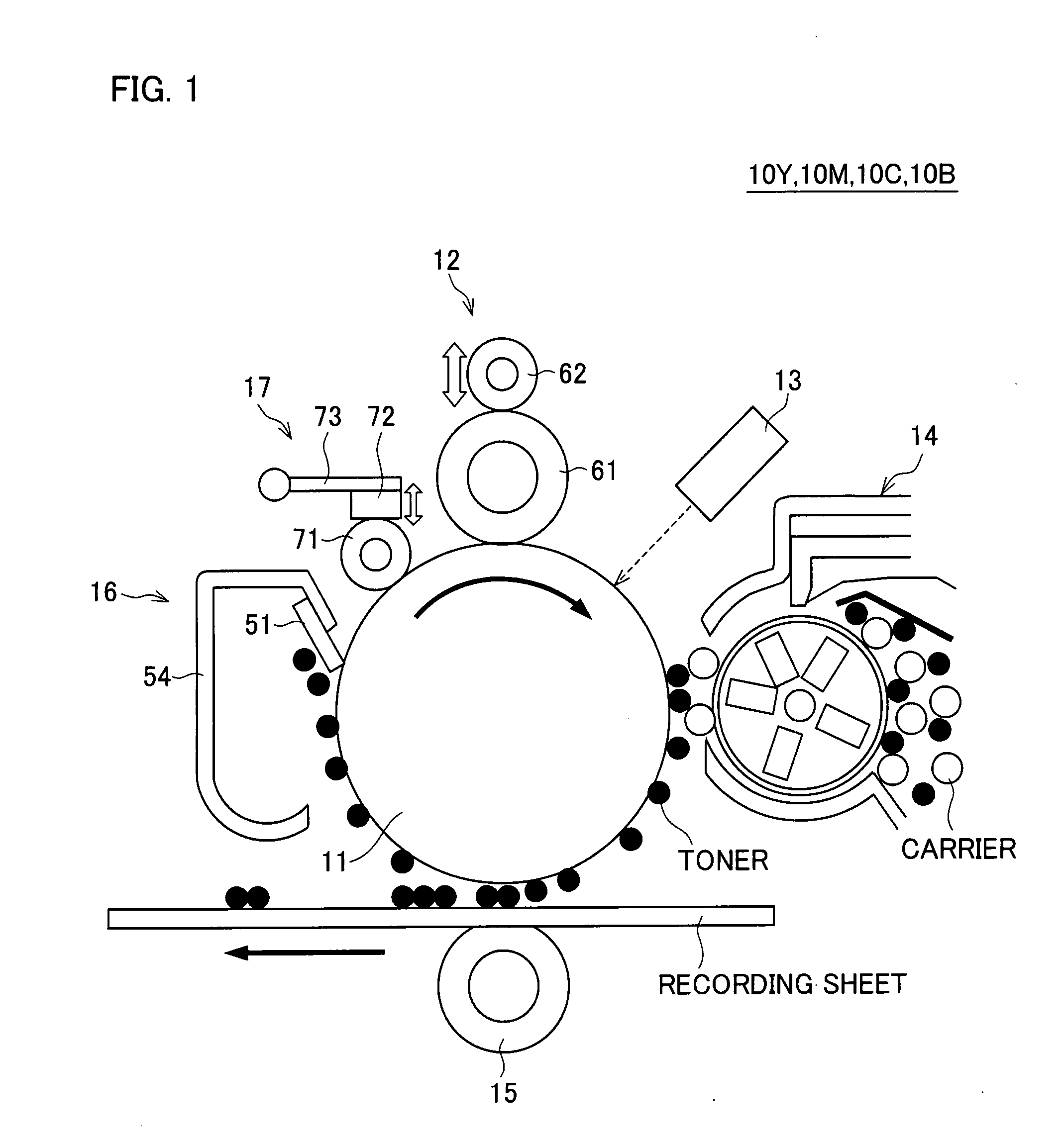
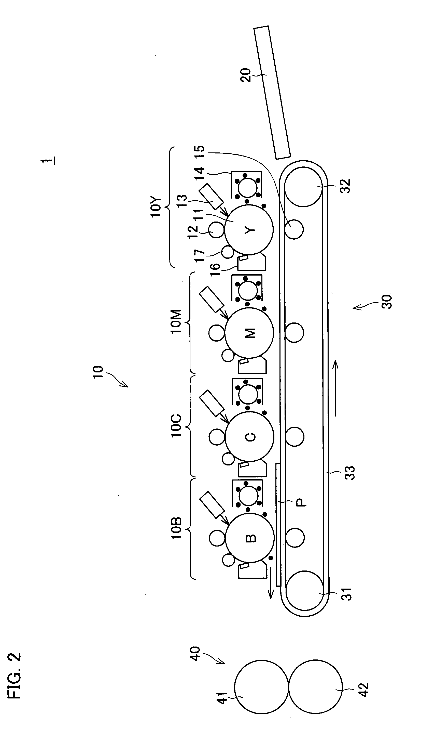
[0032]FIG. 2 is an explanatory drawing schematically illustrating an arrangement of an image forming apparatus 1 according to the present embodiment. The image forming apparatus 1 is an electrophotographic image forming apparatus and forms a multicolor or monochrome image on a recording sheet (transfer medium) in accordance with image data sent from the outside via a network or image data scanned by an image scanning apparatus (not shown) and the like for example.

[0033]As illustrated in FIG. 2, the image forming apparatus 1 includes a visible image forming unit 10, a recording sheet transport section 30, a fixing apparatus 40, and a supply tray 20.

[0034]In the visible image forming unit 10, four visible image forming units 10Y, 10M, 10C, and 10B are provided side by side so as to respectively correspond to yellow (Y), magenta (M), cyan (C), and black (B). That is, the visible image forming unit 10 i...


PUM


Abstract

Along a rotational direction of a photoreceptor, a cleaner unit for cleaning a surface of the photoreceptor, a lubricant applying apparatus for applying a lubricant to the surface of the photoreceptor, and a charging device for charging the surface of the photoreceptor are disposed in this order. Further, the lubricant applying apparatus applies the lubricant to the surface of the photoreceptor which has been cleaned and has not been charged. As a result, it is possible to uniformly apply the lubricant to the surface of the image carrier for an extended period of time with stability.

Description

[0001]This Nonprovisional application claims priority under 35 U.S.C. §119(a) on Patent Application No. 127058 / 2006 filed in Japan on Apr. 28, 2006, the entire contents of which are hereby incorporated by reference.FIELD OF THE INVENTION[0002]The present invention relates to (i) a lubricant applying apparatus for applying a lubricant to an image carrier provided on an electrophotographic image forming apparatus, (ii) an image forming apparatus, (iii) a control method of the image forming apparatus, (iv) a program, and (v) a storage medium of the program.BACKGROUND OF THE INVENTION[0003]In an electrophotograph scheme adopted in an image forming apparatus such as a copying machine and a laser printer, a surface of a photoreceptor (image carrier) is charged by a charging device, and then exposure is carried out by an exposing device so as to form an electrostatic latent image, and the electrostatic latent image is developed by a developing device, thereby forming a toner image. The ton...

Claims


Application Information

Patent Timeline
Patent Type & Authority Applications(United States)
IPC IPC(8): G03G15/02G03G21/00
CPCG03G15/0216G03G21/0011G03G21/00
Inventor KAGAWA, TOSHIAKI
Owner SHARP KK
Why Eureka
Try Eureka