
Wire structure of a power supply

a power supply and wire structure technology, applied in the direction of gaseous cathodes, electric apparatus casings/cabinets/drawers, instruments, etc., can solve the problems of inability to operate and work well, waste of existing resources, complex layout, etc., to prevent the difficulty of arrangement, simple manufacturing, and good expandability

Inactive Publication Date: 2007-11-01
ANDYSON INT
View PDF10 Cites 3 Cited by
  • Summary
  • Abstract
  • Description
  • Claims
  • Application Information

AI Technical Summary

Benefits of technology

"The present invention provides an improved power supply for a computer with a simple wire structure that is easy to manufacture and expand. The wire structure includes a cluster of connection wires, a motherboard power cord, and at least one power cord set. The cluster of connection wires is connected to the power circuit, and the power cord set has a connector that can be connected to different expansion equipment for different specifications. This design simplifies the manufacturing process and reduces the time for allocation processing. The power cord set can be easily replaced and provides multiple power connectors for different specifications, which eliminates the concern of power connector insufficiency and simplifies the wiring layout to prevent the influence of computer function. Overall, the present invention provides a flexible and expandable power supply for computer with improved efficiency and ease of use."

Problems solved by technology

However, without the power supply cannot operate and work well.
With the future development, change of computer technology and a growing increment of personal demand, such kind design and construction of power supply with wire structure / accessory elements are not sufficient and therefore will be easily phased out.
It will result in the waste of existing resource.
Furthermore, under a condition of coping with an increment of expansion equipment, an intricate and complicated layout will be formed in an interior of the computer casing by transfixing the power cord set from a same place, which is hard to arrange and is even able to cause insufficient heat dissipation inside the computer casing.
However, the process of additional manufacturing the female junctions will be very complicated and the other circuit-board should be manufactured which results in high cost and the condition of easily and potentially short-circuited happened.

Method used


Image

  • Wire structure of a power supply
  • Wire structure of a power supply
  • Wire structure of a power supply

Examples


Embodiment Construction

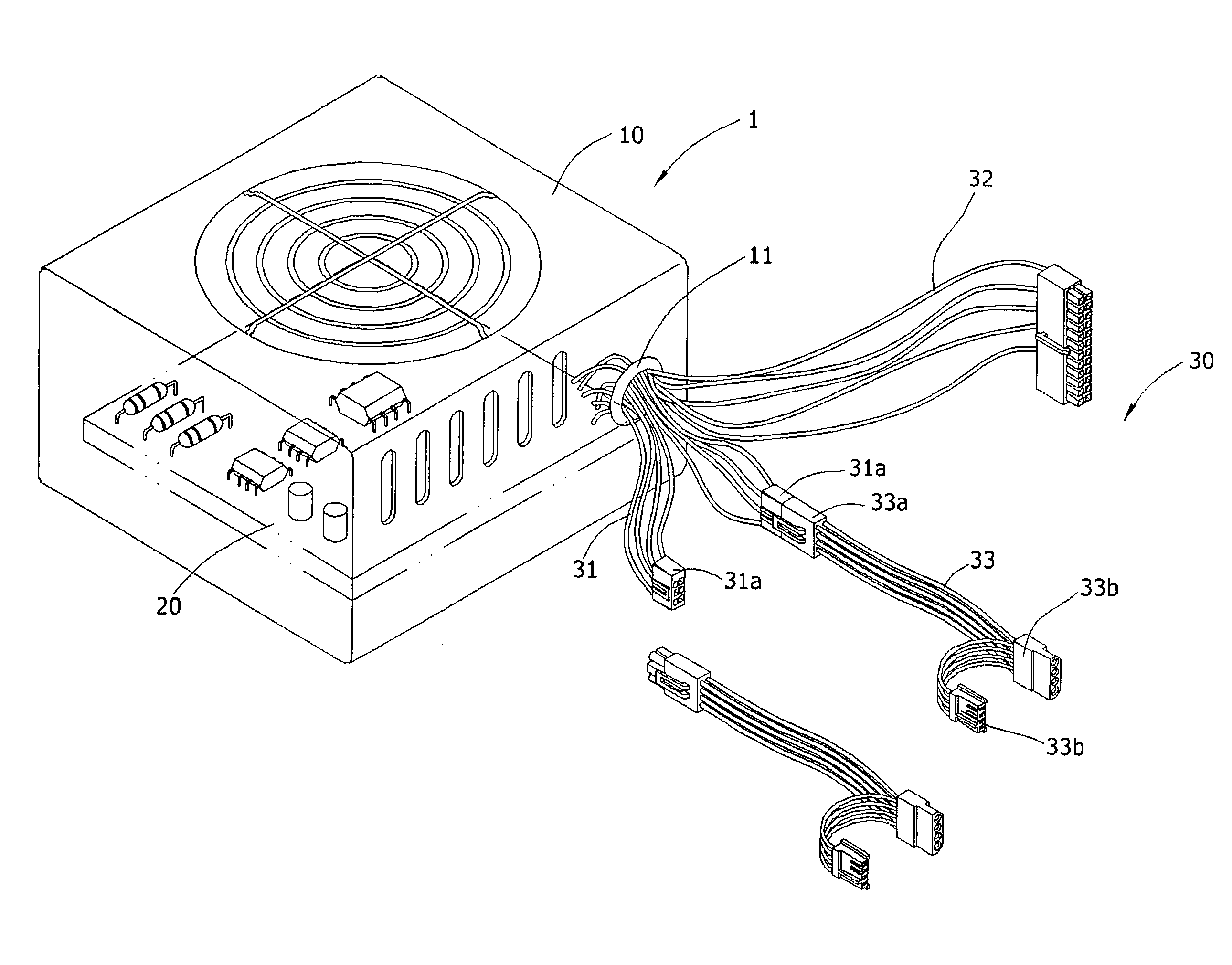
[0017] Referring to FIG.-3□ FIG-4□ FIG-5, the interior of power supply 1's casing 10 is provided with a power circuit 20 for transforming and regulating the input / output voltage, and the wire structure 30 for the output of power source is transfixed out from an opening 11 on the casing 10. The wire structure 30 is composed of “cluster of connection wires 31”, “motherboard power cord 32”, and at least one “power cord set 33”. Wherein the tail end of the cluster of connection wires 31 is connected with the plurality of connection seats 31a. The motherboard power cord 32 is connected into a corresponding socket on the motherboard. It is transfixed out of the same opening 11 along with the aforementioned cluster of connection wires 31, or is independently transfixed out of an opening 12 located closely to the motherboard socket to improve the shortcoming of an additional wiring to the motherboard. One end of the power cord set 33 with a connector 33a insert into the connection seat 31a,...


PUM


Abstract

A wire structure for a power supply. It includes a power supply having a casing on which a wire structure is transfixed out for outputting the power source. The wire structure is composed of a cluster of connection wires, a motherboard power cord, and at least one power cord set. The cluster of connection wires is provided with a plurality of connection seats for connecting with the power cord set, and the other end of the power cord set is provided with a power connector corresponding to future expanded equipments and elements for various different specifications.

Description

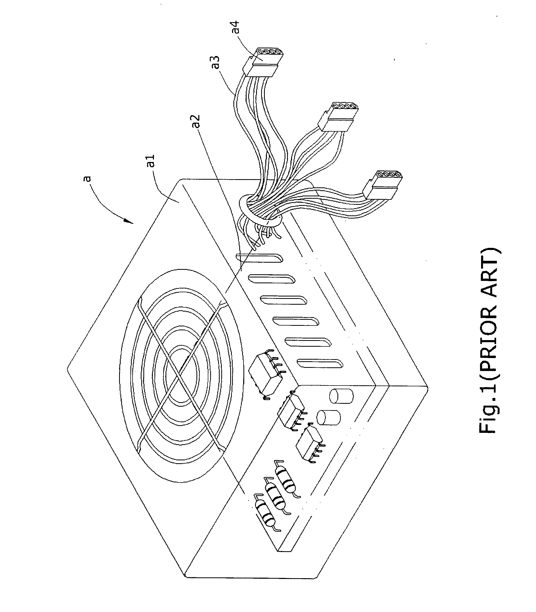
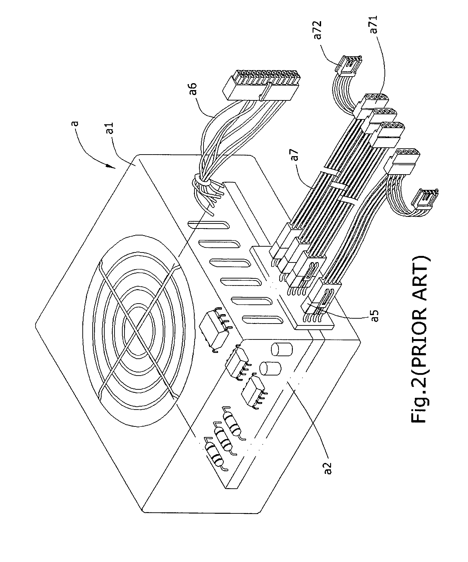
BACKGROUND OF THE INVENTION [0001] (a) Field of the Invention [0002] The present invention is related to a wire structure of a power supply, and more particularly to a wire structure of output of a power supply, which provides a cluster of connection wires and a plurality of power cord sets having power connectors corresponding to various expanded equipments with different specifications. [0003] (b) Description of the Prior Art [0004] The computer is very popular that every home and each company use computer. It is combined with central processing unit(CPU), Motherboard, any kinds of slots, interface cards (such as display card and audio card and so on), hard disk, floppy disk and CD-ROM disk emplaced within the case of the computer. However, without the power supply cannot operate and work well. Referring to FIG. 1, the traditional power supply A of computer includes a casing A1, and an interior installed with a power circuit A2 for transforming and regulating the voltage. A bundle...

Claims


Application Information

Patent Timeline
Patent Type & Authority Applications(United States)
IPC IPC(8): H01R11/00
CPCH02M7/003G06F1/189
Inventor CHANG, HSING-TING
Owner ANDYSON INT
Learn More