

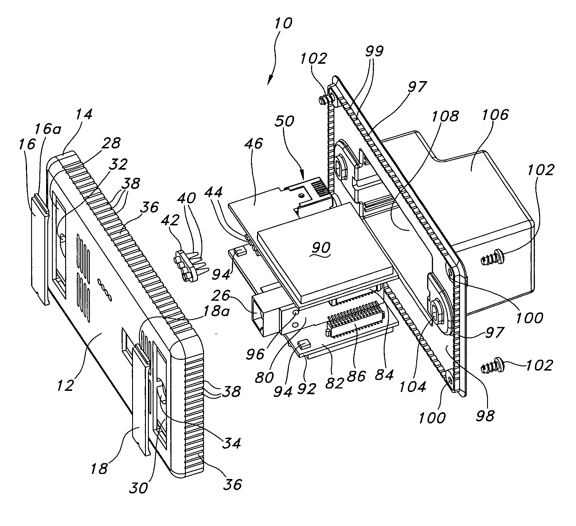
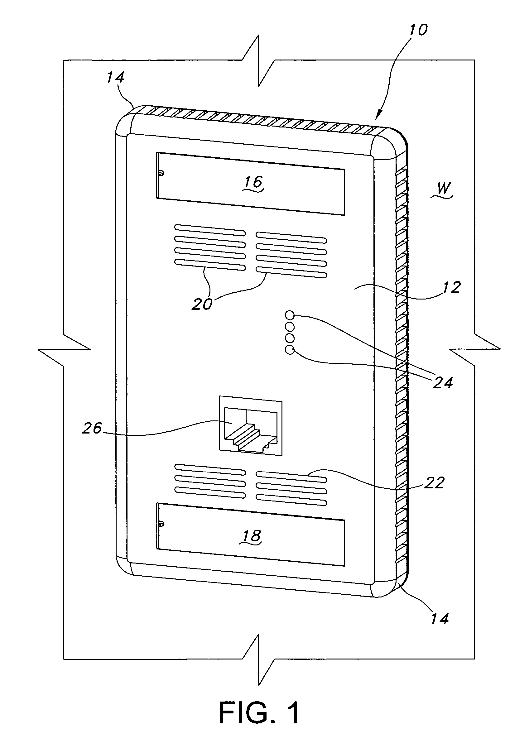
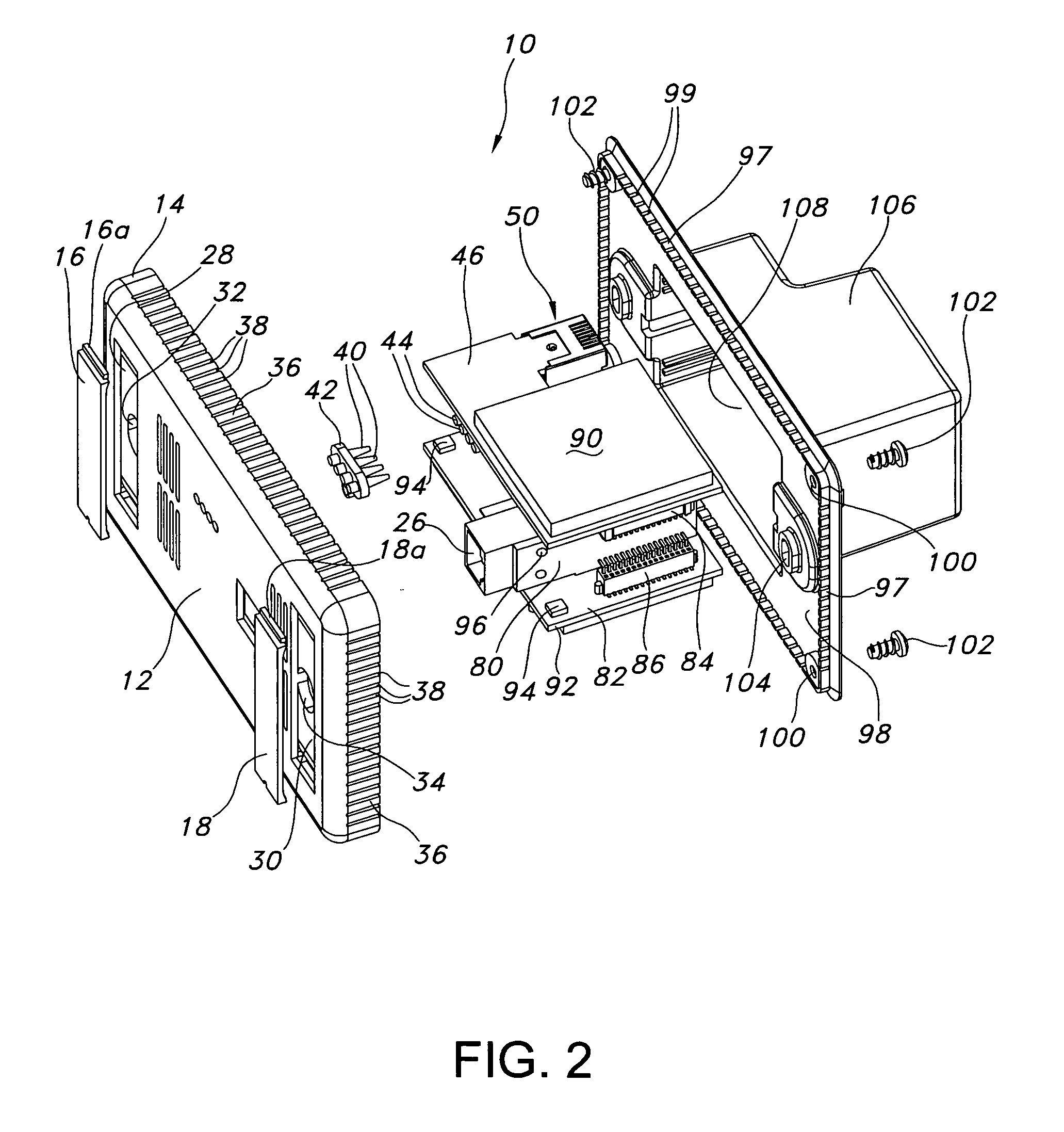
Plug assembly including integral printed circuit board
a printed circuit board and plug assembly technology, applied in the direction of coupling devices, electrical components, coupling devices, etc., can solve the problems of inability to meet the requirements of the desired environment, etc., to achieve convenient wiring connections, avoid potential damage to electrical components, and enhance the effect of wiring eas
- Summary
- Abstract
- Description
- Claims
- Application Information
AI Technical Summary
Benefits of technology
Problems solved by technology
Method used
Image

Examples
Embodiment Construction
)
[0030] As described herein with reference to exemplary embodiment(s), the present disclosure provides access points, access point systems and access point-related components, subassemblies and support structures that, alone or in combination, support a host of communication applications. The disclosed access points and access point systems include and / or support wireless functionality. Thus, in exemplary embodiments of the present disclosure, the disclosed access points include one or more antennae that are adapted to transmit and receive wireless communications. The disclosed access points also include a printed circuit board layout that supports, inter alia, the disclosed antennae and a full range of signal / data processing functionalities, e.g., Ethernet-based signal transmission / receipt functionalities. Power is delivered to the disclosed access point components through Power-over-Ethernet (PoE) techniques, as are known in the art.
[0031] As used herein, “Power-over-Ethernet” or...
PUM
 Abstract
Description
Claims
Application Information