Assembly for extracting heat from a housing for electronic equipment

Active Publication Date: 2007-11-01
EATON INTELLIGENT POWER LIMITED
View PDF7 Cites 55 Cited by
  • Summary
  • Abstract
  • Description
  • Claims
  • Application Information

AI Technical Summary

Benefits of technology

[0004]It is therefore an object of this invention to provide a rack cooling system that

Problems solved by technology

The electronic equipment generates substantial heat that must be dissipated.
However, such thickened panels in

Method used


Image

  • Assembly for extracting heat from a housing for electronic equipment
  • Assembly for extracting heat from a housing for electronic equipment
  • Assembly for extracting heat from a housing for electronic equipment

Examples


Example

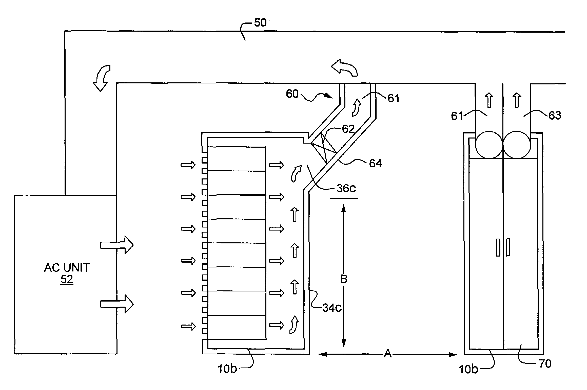
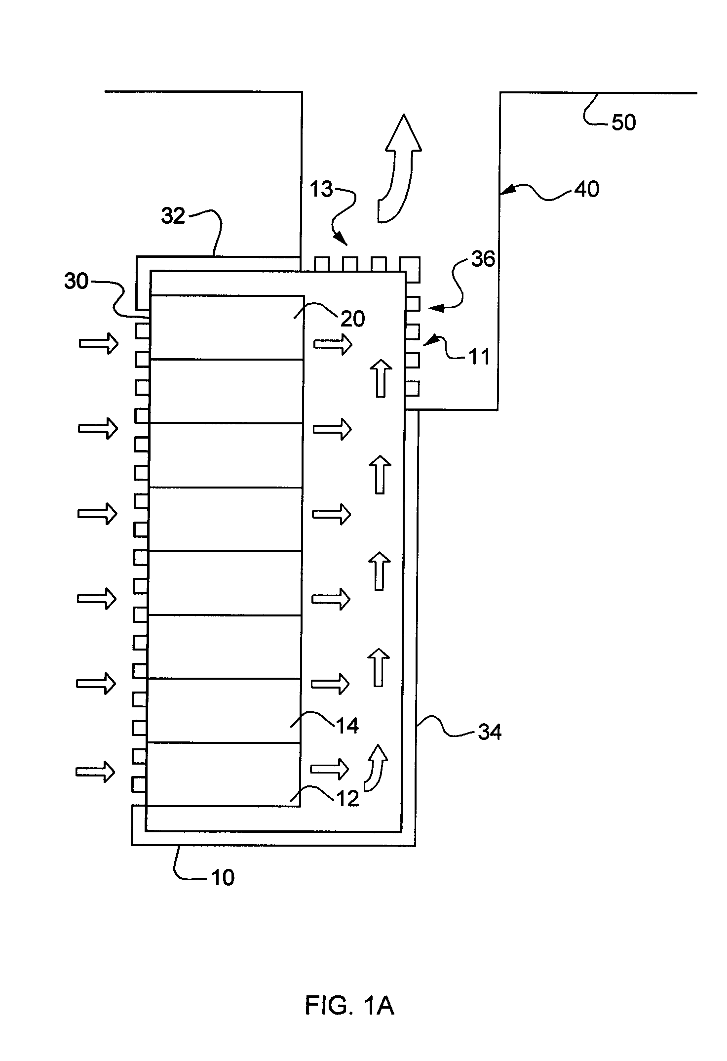
[0016]This invention may be accomplished in an assembly for extracting heat from a housing for electronic equipment, the housing having a front, a back, two sides and a top, the assembly comprising a back for the housing that defines an open area proximate the top, and an air passageway in fluid communication with the open area in the back, to conduct heated air exiting the housing through the open area away from the housing. Typically, the front is perforated and the sides are solid, so that air flows into the housing through the front, through the electronic equipment located in the housing, and out of the housing through the open area, into the passageway.

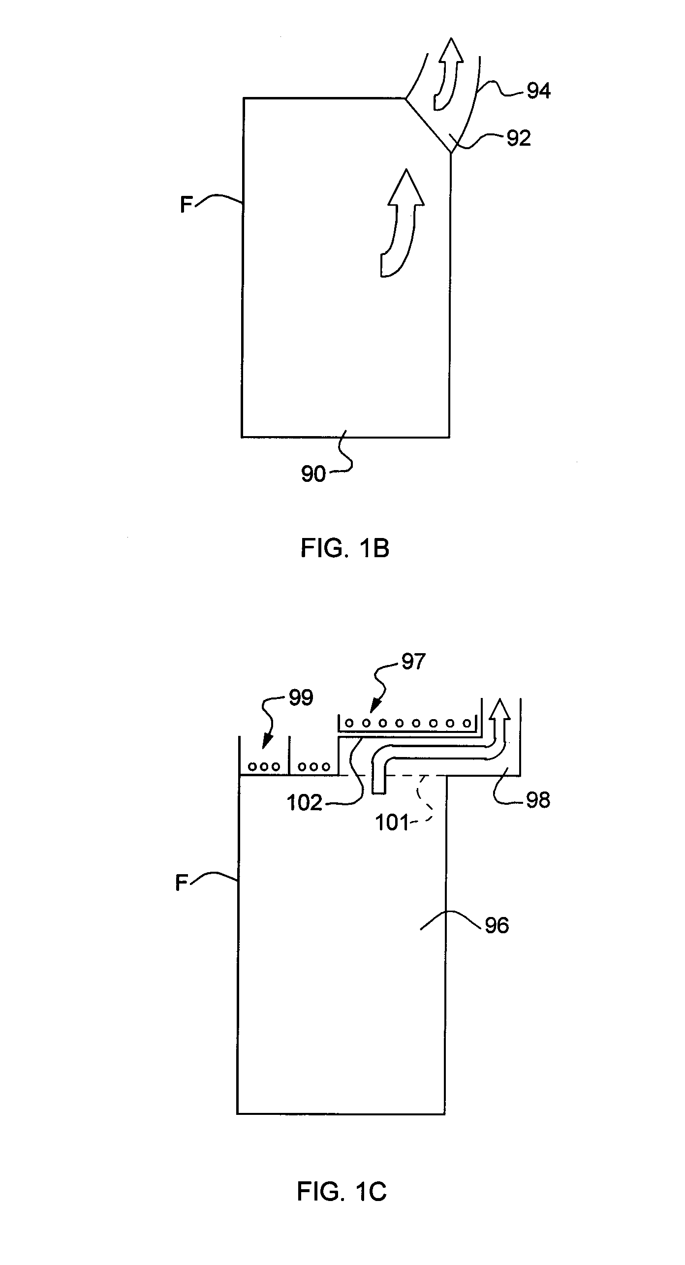
[0017]FIGS. 1A-1C schematically depict three concepts for accomplishing the invention, which is an assembly for extracting heat from a housing for electronic equipment. In this case, housing 10 may be a computer server rack such as a “Paramount” enclosure offered by Wright Line LLC of Worcester, Mass. Computer equipment rack 10 ...


PUM


Abstract

An assembly for extracting heat from a housing for electronic equipment, the housing having a front, a back, two sides and a top. The assembly is defined by a back for the housing that defines an open area proximate the top, and an air passageway in fluid communication with the open area in the back, to conduct heated air exiting the housing through the open area away from the housing.

Description

FIELD OF THE INVENTION[0001]This invention relates to a housing for electronic equipment with improved heat-dissipation characteristics.BACKGROUND OF THE INVENTION[0002]Electronic equipment is often located within a housing, such as an equipment rack used to hold computer servers and the like in assemblies that are located within the rack. The electronic equipment generates substantial heat that must be dissipated. Cool air typically passes through the housings to help dissipate heat. In many cases, fans located in the front door and / or back door and / or within the rack and / or in the top of the rack are used to circulate the cold air and expel the warmed air.[0003]One solution proposes a front or back rack panel that is several inches thick, and carries ducting and fans to route air through the rack. Cool air enters the bottom of the front, and exits the top of the back. However, such thickened panels increase the depth of the racks, which inherently limits the number of racks that c...

Claims


Application Information

Patent Timeline
IPC IPC(8): H05K5/00
CPCH05K7/20745
Inventor GERMAGIAN, MARKPRUNIER, JOHNOLSEN, MARTIN
Owner EATON INTELLIGENT POWER LIMITED
Why Eureka
Try Eureka