
Particulate Matter Remaining Amount Estimating Method for Particulate Filter and Particulate Filter Regenerating Method

Inactive Publication Date: 2007-11-08
TOYOTA JIDOSHA KK
View PDF2 Cites 13 Cited by
  • Summary
  • Abstract
  • Description
  • Claims
  • Application Information

AI Technical Summary

Benefits of technology

[0008] In view of the foregoing problems, this invention thus provides technology that enables the amount of PM remaining on the filter during execution of filter regeneration control to be estimated with greater accuracy.

Problems solved by technology

Further, when the filter regeneration control is stopped prematurely, i.e., when the filter regeneration control is stopped while there is still PM on the filter, and the PM remaining amount at the time that the filter regeneration control was stopped is not known, it also becomes difficult to know the PM accumulation amount after that point.
As a result, the next cycle of filter regeneration control might not be able to be started at the appropriate timing.

Method used


Image

  • Particulate Matter Remaining Amount Estimating Method for Particulate Filter and Particulate Filter Regenerating Method
  • Particulate Matter Remaining Amount Estimating Method for Particulate Filter and Particulate Filter Regenerating Method
  • Particulate Matter Remaining Amount Estimating Method for Particulate Filter and Particulate Filter Regenerating Method

Examples


Embodiment Construction

[0040] In the following description and the accompanying drawings, the present invention will be described in more detail in terms of exemplary embodiments.

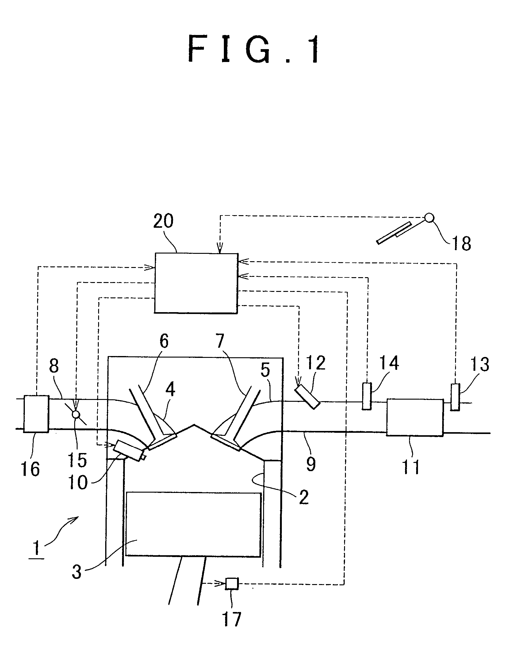
[0041] A first exemplary embodiment of the invention will first be described. FIG. 1 is a schematic diagram of an internal combustion engine and intake and exhaust systems thereof according to this exemplary embodiment. The internal combustion engine 1 is a diesel engine for driving a vehicle. A piston 3 is slidably provided in a cylinder 2 of the internal combustion engine 1. An intake port 4 and an exhaust port 5 are connected to a combustion chamber in an upper portion in the cylinder 2. The portion of the intake port 4 which is open to the combustion chamber is opened and closed by an intake valve 6, and the portion of the exhaust port 5 which is open to the combustion chamber is opened and closed by an exhaust valve 7. The intake port 4 is connected to an intake passage 8 and the exhaust port 5 is connected to an exhaust pa...


PUM


Abstract

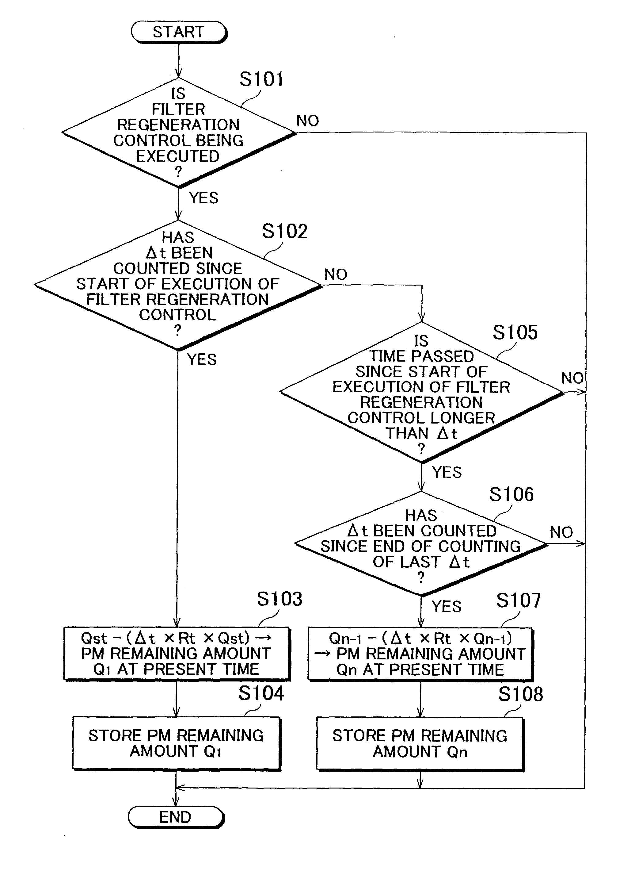
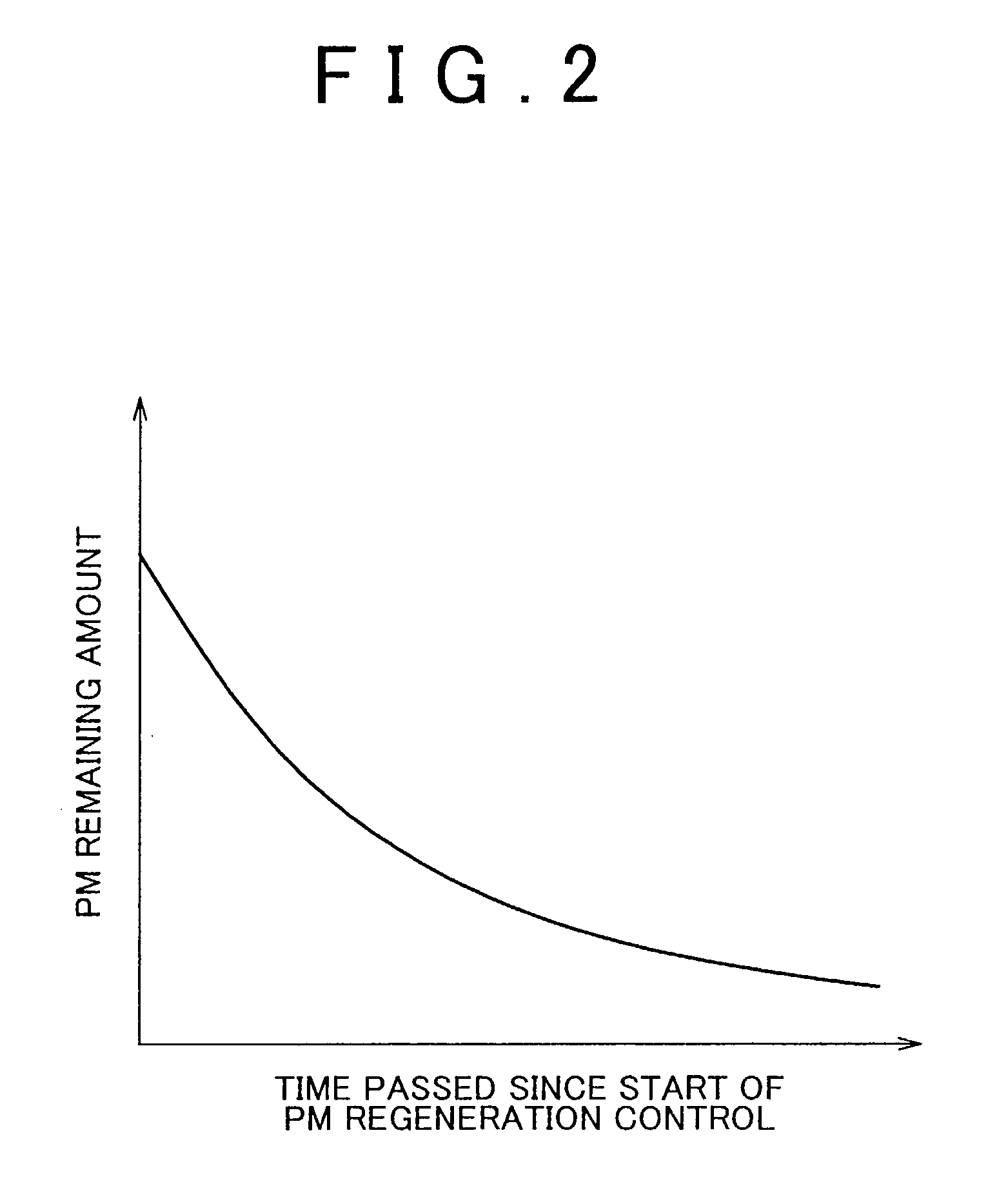
Every time a specified period of time is counted during execution of filter regeneration control, a PM remaining amount every time that the specified period of time passes is estimated by subtracting the product of the specified period of time, a PM removal rate per unit time, and a PM remaining amount at the point when the specified period of time started to be counted from the PM remaining amount at the point when the specified period of time started to be counted. As a result, the PM remaining amount during execution of filter regeneration control which oxidizes and removes particulate matter that has accumulated on a particulate filter is estimated with greater accuracy.

Description

BACKGROUND OF THE INVENTION [0001] 1. Field of the Invention [0002] The invention relates to a method for estimating the amount of particulate matter remaining on a particulate filter, which is provided in an exhaust passage of an internal combustion engine and traps particulate matter contained in exhaust gas, during filter regeneration control which oxidizes and removes particulate matter that has accumulated on the particulate filter. The invention also relates to a method for regenerating a particulate filter. [0003] 2. Description of the Related Art [0004] In an internal combustion engine provided with a particulate filter (hereinafter simply referred to as “filter”) that traps particulate matter (hereinafter simply referred to as “PM”) in exhaust gas in an exhaust passage, filter regeneration control is performed which oxidizes and removes PM that has accumulated on the filter by raising the temperature of the filter. [0005] Further, JP(A) 2003-293733 discloses technology whic...

Claims


Application Information

Patent Timeline
IPC IPC(8): F01N3/023F01N9/00
CPCF01N3/023Y02T10/47F01N9/002F01N3/0253Y02T10/40
Inventor KOGO, TOMOYUKIHASHIZUME, TAKESHI
Owner TOYOTA JIDOSHA KK
Learn More