
Methods of Making LED Extractor Arrays

a technology of extractor arrays and led strips, which is applied in the direction of glass tempering devices, lighting and heating devices, instruments, etc., can solve the problems of limited success of conventional encapsulants, poor achievable brightness of led strips, and waste of light generated by dies

Active Publication Date: 2007-11-08
3M INNOVATIVE PROPERTIES CO
View PDF47 Cites 71 Cited by
  • Summary
  • Abstract
  • Description
  • Claims
  • Application Information

AI Technical Summary

Benefits of technology

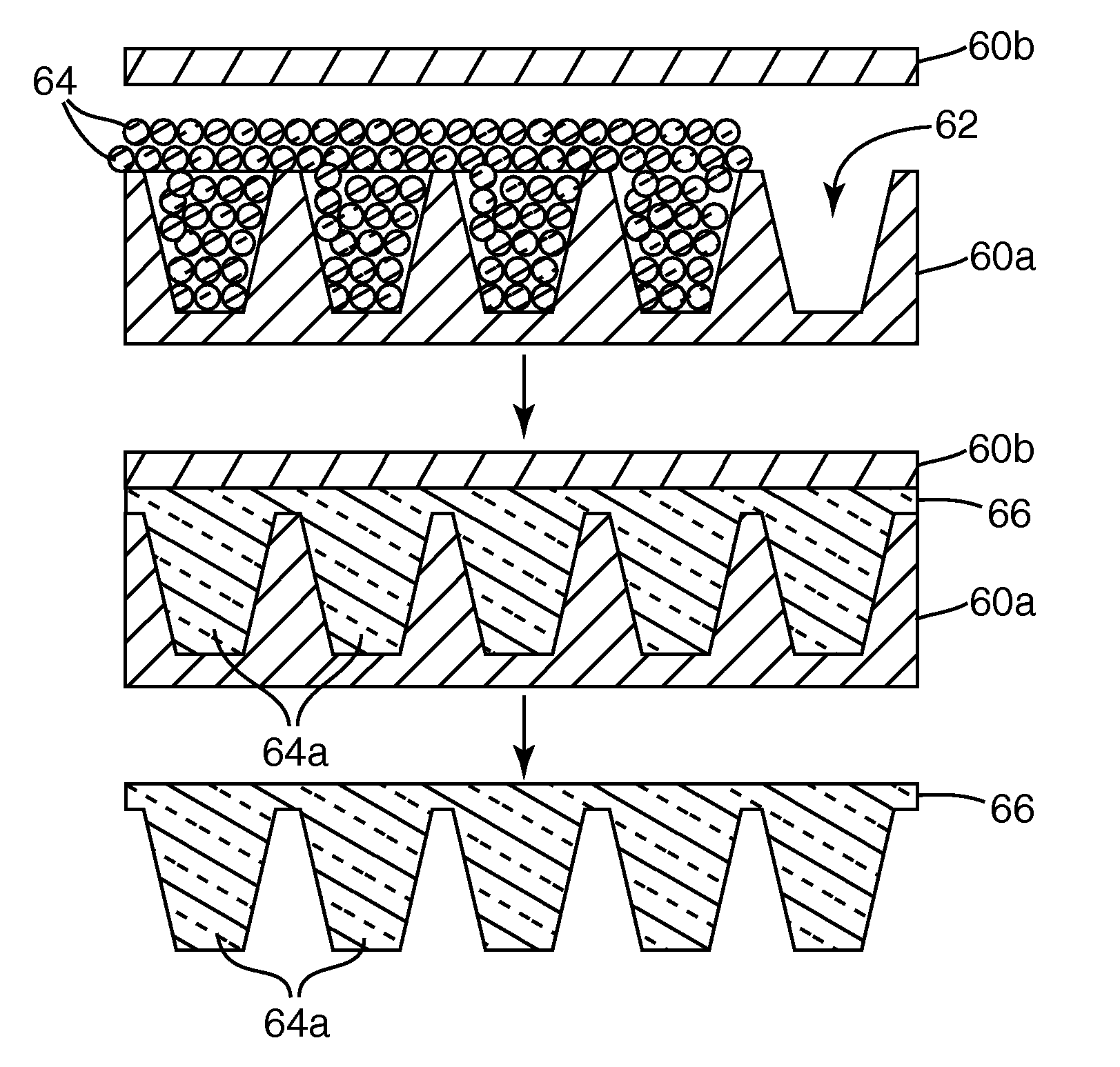
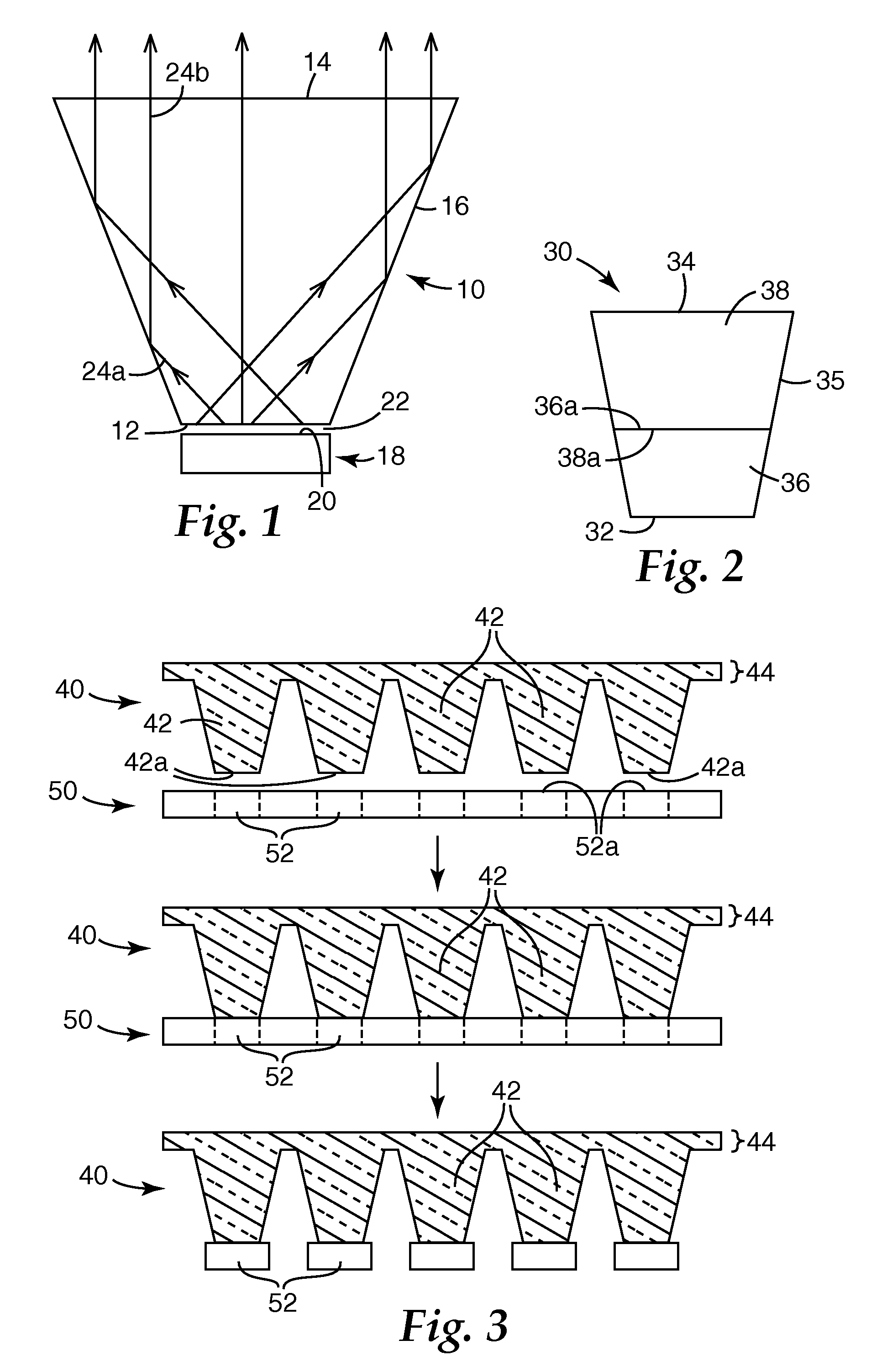
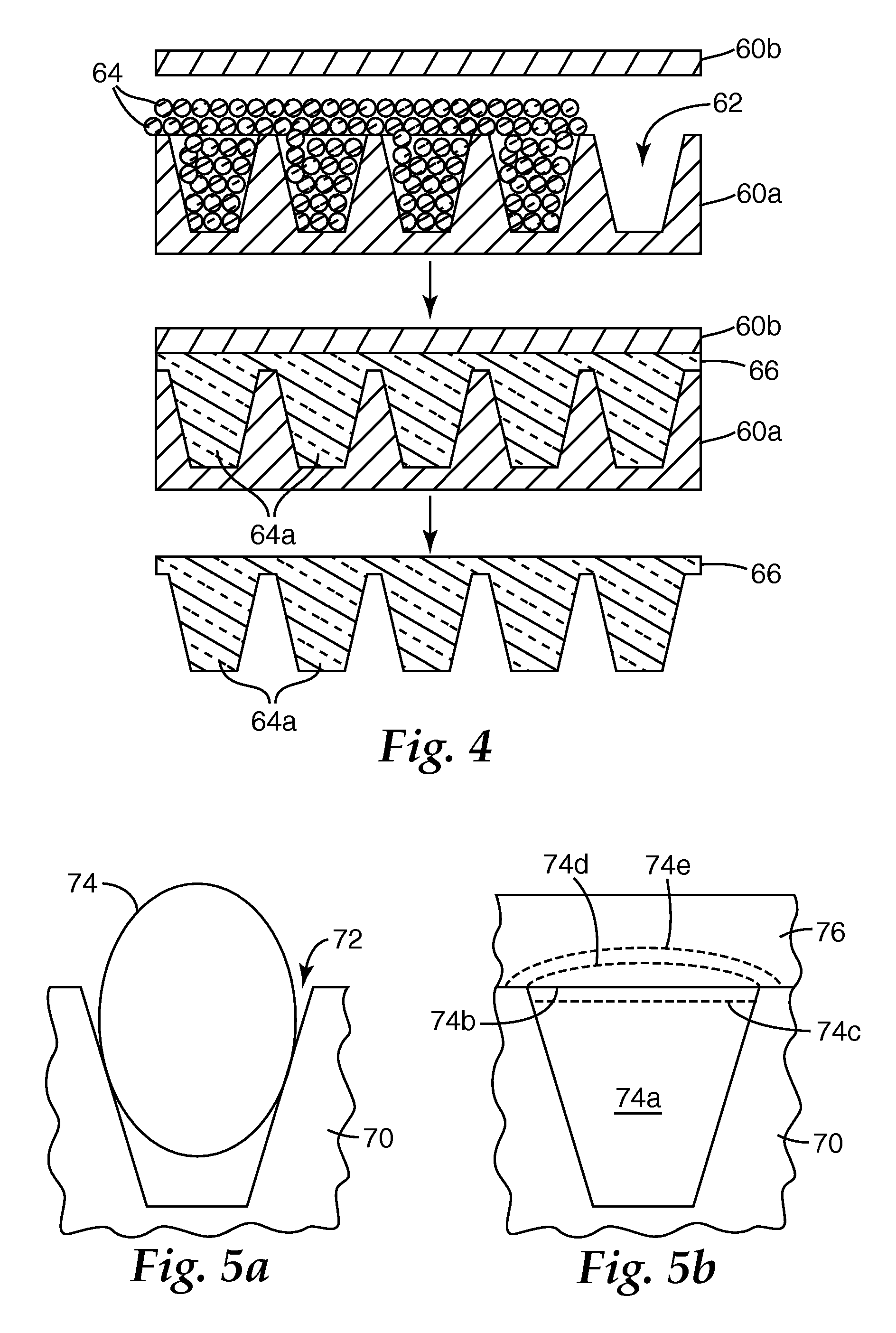
[0009] The present application discloses, inter alia, methods of making extractors suitable for use in LED light sources more easily and economically. The methods involve making a plurality of extractors, typically tens or hundreds, simultaneously using a glass molding operation. The molding operation produces an extractor array by providing a mold having a plurality of cavities therein, each cavity being adapted to form an extractor suitable for coupling to an LED die; filling the mold with a plurality of glass particles; heating the glass particles above glass transition temperatures thereof so that the particles are reshaped to conform to the cavity shapes; and forming a land layer that extends between the cavities. The land layer maintains the extractors in a fixed spatial relationship with each other for subsequent handling or processing, such as a simultaneous polishing operation or in attaching the extractor array to a corresponding LED array.

Problems solved by technology

As a result, much of the light generated by the die is wasted, and the achievable brightness of the LED suffers.
From a practical standpoint, conventional encapsulants have been successful to only a limited extent in this regard.
Extractors are currently not as widely used in LEDs as encapsulants, possibly due to additional manufacturing steps needed to first fabricate the extractor and then hold it in position at the LED die, and the associated expense and complexity.
These problems are exacerbated by the small sizes involved, with LED dies typically having a characteristic dimension on the order of millimeters or less.

Method used


Image

  • Methods of Making LED Extractor Arrays
  • Methods of Making LED Extractor Arrays
  • Methods of Making LED Extractor Arrays

Examples


Embodiment Construction

[0018] The following Description describes light emitting diode (LED) light sources and components therefor. In this regard, “light emitting diode” or “LED” refers to a diode that emits light, whether visible, ultraviolet, or infrared. It includes incoherent encased or encapsulated semiconductor devices marketed as “LEDs”, whether of the conventional or super radiant variety, and whether of the forward-emitting or side-emitting variety, the latter of which is often advantageous in display applications. If the LED emits non-visible light such as ultraviolet light, and in some cases where it emits visible light, it can be packaged to include an organic or inorganic phosphor (or it may illuminate a remotely disposed phosphor) to convert short wavelength light to longer wavelength visible light, in some cases yielding a device that emits white light. An “LED die” is an LED in its most basic form, i.e., in the form of an individual component or chip made by semiconductor processing proce...


PUM

PropertyMeasurementUnit
Fractionaaaaaaaaaa
Fractionaaaaaaaaaa
Surface roughnessaaaaaaaaaa

Abstract

A molding operation produces an extractor array by providing a mold having a plurality of cavities therein, each cavity being adapted to form an extractor suitable for coupling to an LED die; filling the mold with a plurality of glass particles; heating the glass particles above glass transition temperatures thereof so that the particles are reshaped to conform to the cavity shapes; and forming a land layer that extends between the cavities. The land layer maintains the extractors in a fixed spatial relationship with each other for subsequent handling or processing, such as a simultaneous polishing operation or in attaching the extractor array to a corresponding LED array.

Description

FIELD OF THE INVENTION [0001] The present invention relates generally to light emitting diodes (LEDs), and in particular to optical components or elements used to extract light generated within an LED die. BACKGROUND [0002] LEDs are a desirable choice of light source in part because of their relatively small size, low power / current requirements, rapid response time, long life, robust packaging, variety of available output wavelengths, and compatibility with modern circuit construction. These characteristics may help explain their widespread use over the past few decades in a multitude of different end use applications. Improvements to LEDs continue to be made in the areas of efficiency, brightness, and output wavelength, further enlarging the scope of potential end-use applications. [0003] LEDs are typically sold in a packaged form that includes an LED die or chip mounted on a metal header. The header can have a reflective cup in which the LED die is mounted, and electrical leads co...

Claims


Application Information

Patent Timeline
IPC IPC(8): C03B19/09
CPCC03B19/09G02B19/0028G02B19/0066
Inventor BARNES, AMY S.ROSENFLANZ, ANATOLY Z.LEATHERDALE, CATHERINE A.OUDERKIRK, ANDREW J.ROLF, JACQUELINE C.
Owner 3M INNOVATIVE PROPERTIES CO
Features
  • Generate Ideas
  • Intellectual Property
  • Life Sciences
  • Materials
  • Tech Scout
  • Unparalleled Data Quality
  • Higher Quality Content
  • 60% Fewer Hallucinations
Learn More