High Strength Spring Steel, High Strength Springs and Manufacturing Method Thereof

Inactive Publication Date: 2007-11-08
NHK SPRING CO LTD
View PDF6 Cites 21 Cited by
  • Summary
  • Abstract
  • Description
  • Claims
  • Application Information

AI Technical Summary

Benefits of technology

[0041] It has been widely known that if a large compressive residual stress is generated on the surface of a spring by shot peening processing, the fatigue strength and corrosion fatigue strength of the spring are enhanced. The magnitude of residual stress distribution by shot peening is related to deformation characteristics of the material, and for example, for the same tensile strength, a material having a smaller yield ratio (yield stress/tensile strength) can obtain a larger compressive residual stress by shot peening. Then, in the present invention, warm shot peening (WSP) is performed on a formed spring steel. The warm shot peening is a method of carrying out the shot peening in a warm temperature range of 150° C.-350° C. As a consequence, the yield point at the time of shot peening of spring steel decreases

Problems solved by technology

However, conventionally, even if the above-described means is used, the increase in the strength can only be achieved up to HRC52 in spring hardness and 1900 MPa in tensile strength from the durability viewpoint.
That is, if the strength of the spring is intensified, the fracture toughness decreases so that the notch sensitivity increases thereby resulting in dispersion in durability and decrease in reliability.
Further, it is also a problem that inclusions acting as notches decrease the durability.
Further, there are also other problems such that adding any special element costs high in order to prevent decrease in fracture toughness, or that adding a large amount of alloy elements increases hardness a

Method used


Image

  • High Strength Spring Steel, High Strength Springs and Manufacturing Method Thereof
  • High Strength Spring Steel, High Strength Springs and Manufacturing Method Thereof
  • High Strength Spring Steel, High Strength Springs and Manufacturing Method Thereof

Examples


Embodiment Construction

[0045] Hereinafter, the preferred embodiment of the present invention will be described in detail. Steel ingot obtained by melting, having chemical composition shown in Table 1, was bloomed and rolled to wire rod material having 13 mm in diameter and 20 mm in diameter. The rod rolling was performed at a rolling end temperature of 869° C. with the steel heated at 1100° C. The rolled material was cooled down with air after the rolling was finished.

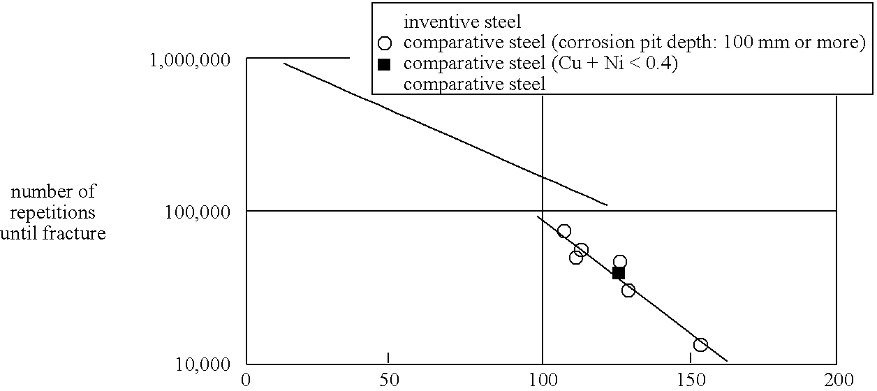
[0046] Table 2 shows values of C(%)+Mn(%)+Cr(%), Si(%) / 3+Cr(%) / 2+Mn(%), Cu(%)+Ni(%) . Of examples deviating from a composition range specified by the present invention in respective compositions in Table, an example which is lower than the lower limit is supplied with a downward arrow and an example which is higher than the higher limit is supplied with an upward arrow ().

TABLE 1CSiMnPSCuNiCrMoupper limit0.482.801.400.0150.0100.502.001.200.50lower limit0.361.700.20——0.100.100.100.01present invention10.402.200.830.0070.0040.290.270.160pre...


PUM

PropertyMeasurementUnit
Temperatureaaaaaaaaaa
Lengthaaaaaaaaaa
Fractionaaaaaaaaaa

Abstract

A high strength spring steel of this invention is characterized in containing, in percent of mass, of C: 0.36-0.48%; Si: 1.80-2.80%; Mn: 0.20-1.40%; P: 0.015% or less; S: 0.010% or less; Cu: 0.10-0.50%; Ni: 0.10-2.00%; Cr: 0.05-1.20%; s-Al: 0.005-0.040%; N: 0.002-0.012%; O: 0.002% or less, while the remainder is constituted of Fe and inevitable impurities and the quantity of inclusions of 10 μm or larger in diameter per field of vision of 100 mm2 is 10 or less. A manufacturing method of high strength spring of this invention is characterized in that the high strength spring steel which is tempered to HRC52 or higher is formed into a spring shape by hot forming or cold forming and warm shot peening is carried out so as to produce a high strength spring of 1176 MPa or higher in maximum shearing stress.

Description

RELATED APPLICATIONS [0001] This application is word-for-word translation of PCT Patent Application No. PCT / JP2004 / 012277 filed on Aug. 26, 2004, which is incorporated herein by reference.BACKGROUND OF THE INVENTION [0002] 1. Field of the Invention [0003] The present invention relates to a high strength spring steel, high strength springs and manufacturing method thereof. [0004] 2. Description of the Related Art [0005] In recent years, reduction in amount of emission of carbon dioxide gas has been considered as a problem to be solved from a viewpoint of suppressing global warming. Thus, reduction in weight of a vehicle resulting in enhancement of fuel efficiency has been regarded important in a field of automobiles, so that reduction in weight of a variety of springs such as a suspension coil spring has been sought after. In order to achieve reduction in weight of the spring while maintaining required spring characteristics, it is required to have a high strength spring having desig...

Claims


Application Information

Patent Timeline
IPC IPC(8): C21D9/02C22C38/42
CPCB24C1/10C22C38/04C22C38/06F16F1/021C22C38/42C22C38/50C22C38/34
Inventor KIMURA, KAZUYOSHIKOYAMA, HIROSHITANGE, AKIRAOKUYAMA, ISAMUHISANO, YOSUKEYONEGUCHI, AKIO
Owner NHK SPRING CO LTD
Why Eureka
Try Eureka