Sound-absorbing exhaust nozzle center plug

a center plug and exhaust nozzle technology, applied in machine/engine, machine/engine, vessel construction, etc., can solve the problems of non-folding acoustic liners not being able to adapt to absorb and dissipate sound, and the airframe and engine producing varying amounts of audible nois

Active Publication Date: 2007-11-08
ROHR INC
View PDF49 Cites 44 Cited by
  • Summary
  • Abstract
  • Description
  • Claims
  • Application Information

AI Technical Summary

Problems solved by technology

An airplane's airframe and engines produce varying amounts of audible noise during takeoff and landing.
Thus, though traditional non-folding acoustic liners may not be adaptable to absorb an...

Method used


Image

  • Sound-absorbing exhaust nozzle center plug
  • Sound-absorbing exhaust nozzle center plug
  • Sound-absorbing exhaust nozzle center plug

Examples


Embodiment Construction

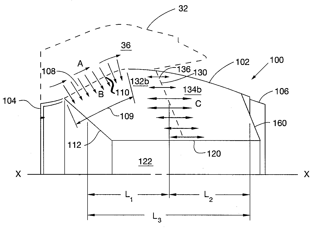
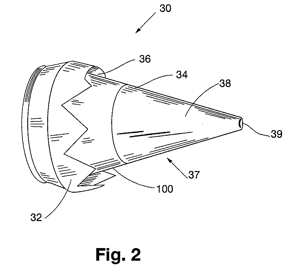
[0026]FIG. 2 shows one embodiment of a combustor exhaust portion 30 of a modern aircraft gas turbine engine. The combustor exhaust portion 30 includes an exhaust nozzle 32 and an exhaust centerbody 37. The centerbody 37 can be formed in two sections including an acoustically treated forward portion (referred to herein as a “center plug”) 100 according to the invention, and an aft cone portion 38. The exhaust nozzle 32 and center plug 100 cooperate to form an annulus 36 through which exhaust gases from the engine's combustor exit the exhaust portion 30 to generate forward thrust. In this embodiment, the center plug 100 and cone portion 38 of the centerbody 37 are connected along a circumferential seam 34 at the aft end of the center plug 100. In the embodiment shown in FIG. 2, the aft portion of the center plug 100 and the attached cone portion 38 extend outwardly from the aft end of the nozzle 32. The outer surfaces of the center plug 100 and the cone 38 combine to form a flow contr...


PUM


Abstract

A sound-absorbing exhaust nozzle center plug for an aircraft gas turbine engine can include an outer skin and at least one forward cavity within the outer skin. At least one aft cavity can be located within the outer skin and substantially aft of the forward cavity. A perforated wall including a plurality of first openings can be disposed between the forward and aft cavities. The outer skin can include a second plurality of openings providing an acoustic pathway through the outer skin and into the forward cavity. The forward and aft cavities can be configured to absorb and dissipate relatively low-frequency sound energy emitted from an aircraft gas turbine engine's combustor.

Description

FIELD [0001] The invention generally relates to aircraft engines, and more particularly relates to an exhaust nozzle center plug having at least one resonator cavity for absorbing and / or dissipating core engine noise at frequencies of about 800 Hz or less. BACKGROUND [0002] An airplane's airframe and engines produce varying amounts of audible noise during takeoff and landing. For example, an aircraft's engines typically operate at or near maximum thrust as the aircraft departs from an airport, and lower thrust as the aircraft approaches an airport. Some aircraft engine noise can be partially suppressed at the engine nacelle inlet and the exhaust nozzle by noise absorbing liners. These liners can absorb acoustic energy by canceling acoustic reflected waves and / or converting acoustic energy into heat, and typically consist of a porous skin supported by an open-cell matrix. The open-cell matrix provides separation between the porous skin and a non-perforated backskin. Some have postula...

Claims


Application Information

Patent Timeline
IPC IPC(8): B64D33/02
CPCF02K1/04F02K1/827F05D2250/283F05D2230/13F05D2260/96
Inventor YU, JIACHIEN, EUGENE W.
Owner ROHR INC
Why Eureka
Try Eureka