Switching voltage regulator with an improved range of input voltage
- Summary
- Abstract
- Description
- Claims
- Application Information
AI Technical Summary
Benefits of technology
Problems solved by technology
Method used
Image
Examples
Embodiment Construction
[0022] The preferred embodiments according to the present invention will be described in detail with reference to the drawings.
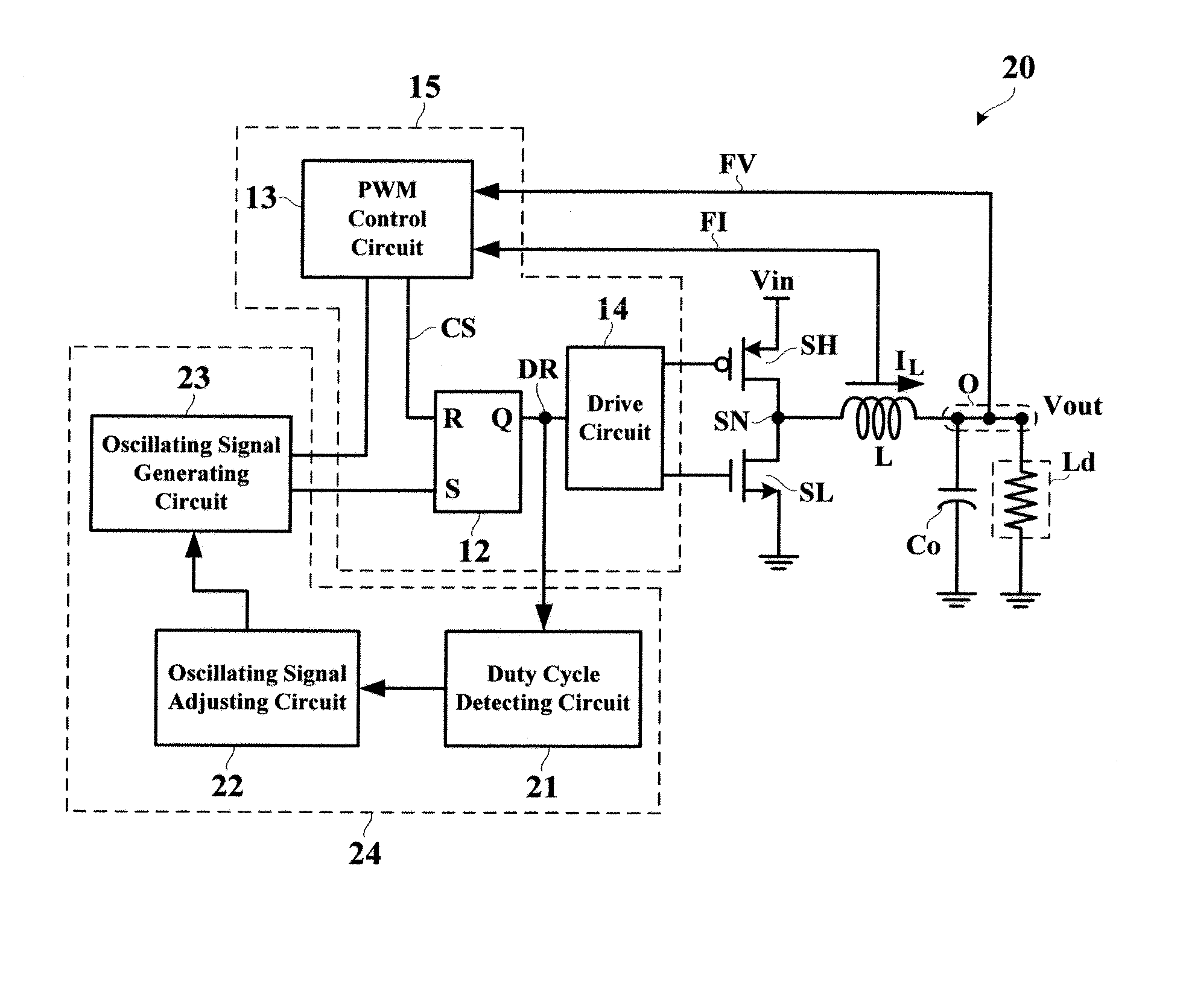
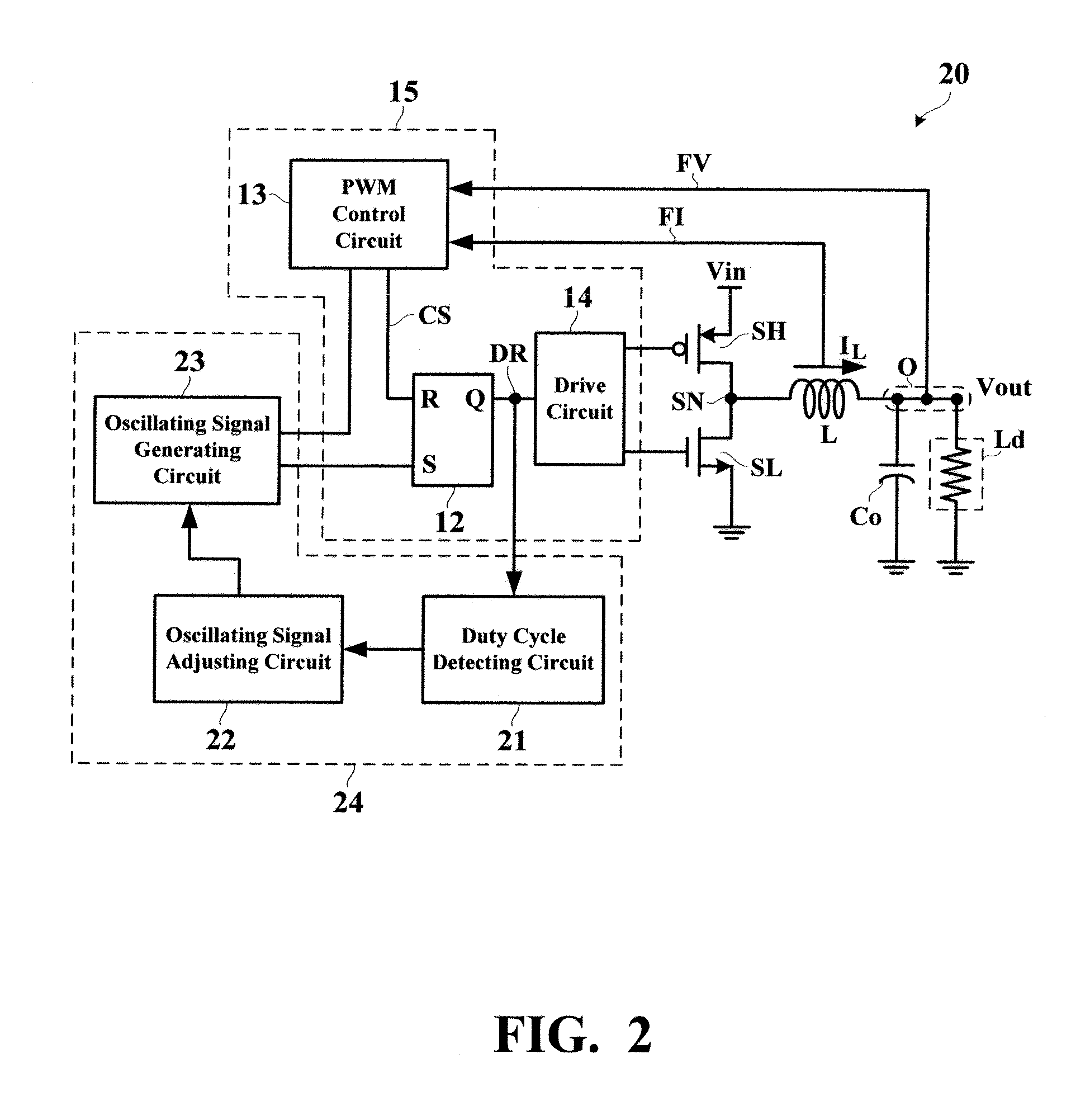
[0023]FIG. 2 is a circuit diagram showing a switching voltage regulator 20 according to a first embodiment of the present invention. The switching voltage regulator 20 belongs to the step-down type, i.e., converting the higher input voltage Vin into the lower output voltage Vout.
[0024] The switching voltage regulator 20 has a switch control system 15 and an oscillating signal generating system 24. The switch control system 15 is constituted by a latch 12, a PWM control circuit 13, and a drive circuit 14. The oscillating signal generating system 24 is constituted by a duty cycle detecting circuit 21, an oscillating signal adjusting circuit 22, and an oscillating signal generating circuit 23.
[0025] More specifically, the duty cycle detecting circuit 21 detects the duty cycle Da of the drive signal DR. When the input voltage Vin becomes closer to the output ...
PUM
 Abstract
Description
Claims
Application Information
 - R&D
- Intellectual Property
- Life Sciences
- Materials
- Tech Scout
- Unparalleled Data Quality
- Higher Quality Content
- 60% Fewer Hallucinations
Browse by: Latest US Patents, China's latest patents, Technical Efficacy Thesaurus, Application Domain, Technology Topic, Popular Technical Reports.
© 2025 PatSnap. All rights reserved.Legal|Privacy policy|Modern Slavery Act Transparency Statement|Sitemap|About US| Contact US: help@patsnap.com


