Methods and systems for automatically rendering information on a display of a building information system

a technology of building information and display methods, applied in the field of information display methods and systems, can solve the problems of first responders not being able to quickly and accurately identify building information on the floor or site plan, and achieve the effects of reducing visual artifacts caused by high contrast, and reducing the number of errors

Active Publication Date: 2007-11-08
HONEYWELL INT INC
View PDF18 Cites 12 Cited by
  • Summary
  • Abstract
  • Description
  • Claims
  • Application Information

AI Technical Summary

Benefits of technology

[0010] Advantageously, adjusting the contrast ratio of the plan image according to the aforementioned method enables the icons and other graphical elements to clearly stand out from the plan image and visual artifacts caused by high contrast are substantially reduced. A first responder viewing the display is able to easily and rapidly identify the important information associated with the site or floor plan, such as elevators, evacuations stairs, activated fire alarms and other building and / or emergency features, represented by the graphical elements so that the first responder can perform an initial assessment of the situation an efficient and effective manner. Adjusting the contrast ratio in the aforementioned manner can also facilitate easier identification of graphical icons displayed in other windows separate from the floor plan.

Problems solved by technology

Typically, the displayed floor or site plan includes background information as well as foreground information representing walls or pathways over which the graphical elements are superimposed or overlaid making it difficult in an emergency situation for the first responder to rapidly and accurately identify the building information on the floor or site plan.

Method used


Image

  • Methods and systems for automatically rendering information on a display of a building information system
  • Methods and systems for automatically rendering information on a display of a building information system
  • Methods and systems for automatically rendering information on a display of a building information system

Examples


Embodiment Construction

[0026] The particular values and configurations discussed in these non-limiting examples can be varied and are cited merely to illustrate an embodiment of the present invention and are not intended to limit the scope of the invention.

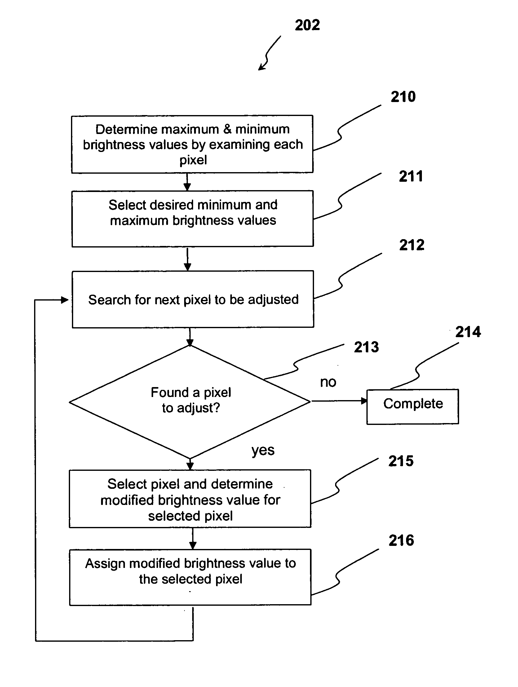
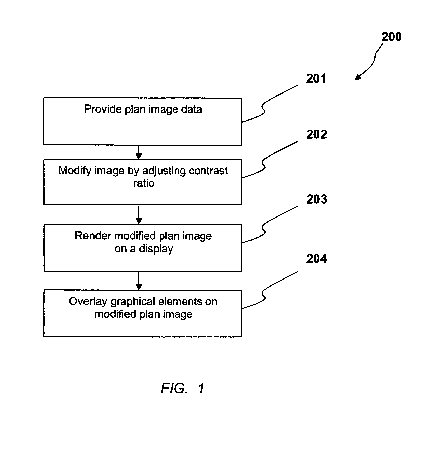
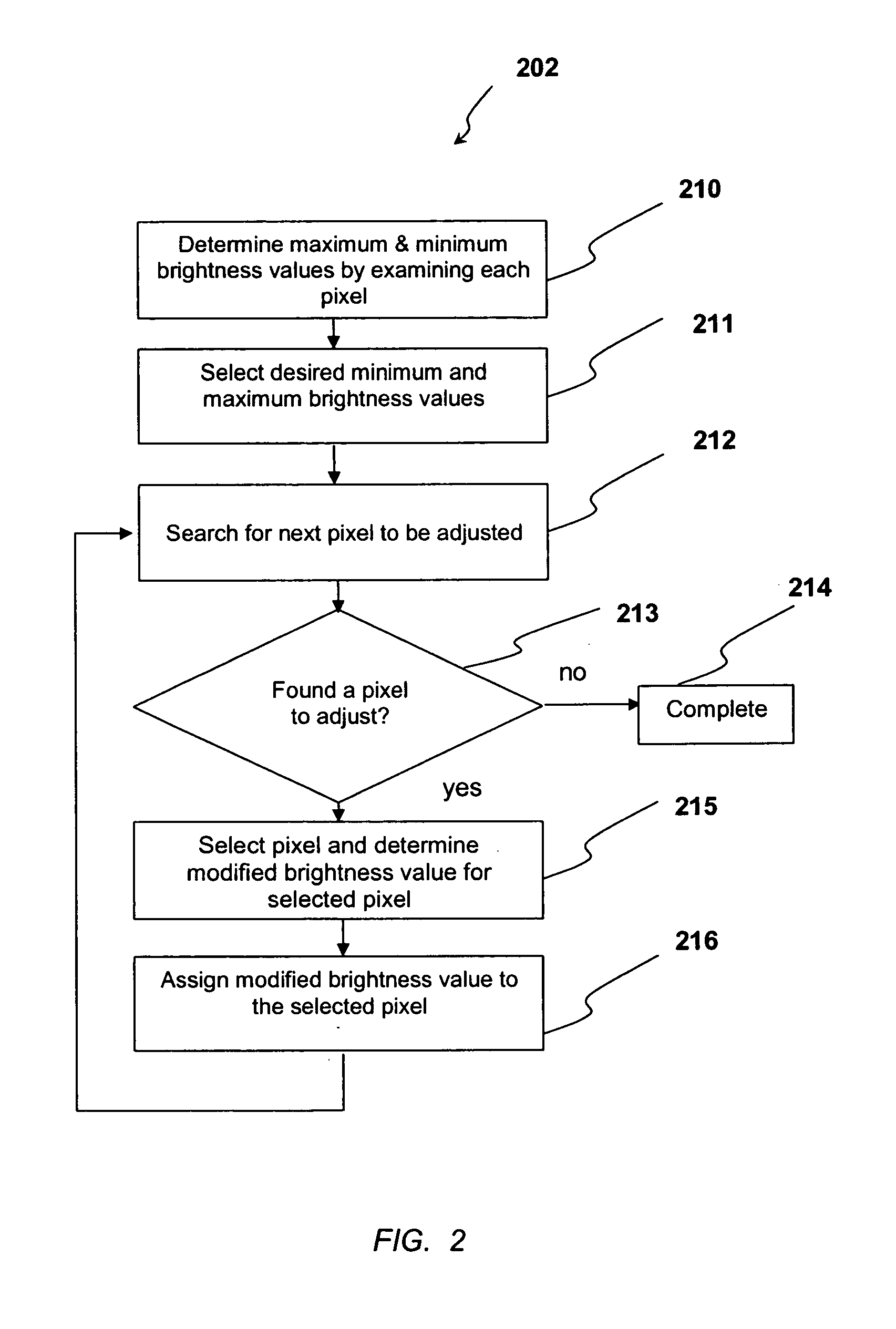
[0027] Referring to FIG. 1 of the accompany drawings, which illustrates a simplified flow chart of general operational steps which may be performed to implement the method for automatically rendering information on a display of a building information system according to one embodiment, as a general overview, a plan image, which can be for example a floor or site plan image, is generated, as indicated in step 201, which is subsequently modified by adjusting the contrast ratio of the plan image (step 202) preparatory to rendering the plan image on a display (step 203) together with graphical elements overlaying the modified plan image (step 204). The overlaid graphical elements represent important information associated with the plan image. As will be ex...


PUM


Abstract

A method, system and computer program product for automatically rendering information on a display screen of a building information system. Following generation of a plan image, such as a floor or site plan image, the plan image is modified and subsequently rendered on the display screen. The plan image is modified by adjusting the contrast ratio of the plan image such that, when graphical elements, such as icons representing elevators, evacuation stairways and fire hydrants, are rendered on the display screen overlaying the modified plan image, the graphical elements are visually distinct from the modified plan image.

Description

TECHNICAL FIELD [0001] Embodiments generally relate to information display methods and systems. Embodiments also relate to methods and systems for rendering information, such as a floor or site plan, on a display of a building information system, particularly a display screen of a first responder building information display system. Embodiments additionally relate to software or hardware modules for implementing such methods. BACKGROUND OF THE INVENTION [0002] Building information display systems are utilized by firefighters or other first responders to improve situation awareness at the fire ground. Current building information display systems are installed on site in lobby or reception areas of buildings and consist of a computer display system which is operable by the first responder to display the site or building information so that the first responder can make an initial assessment of the emergency situation and plan appropriate action. [0003] The first responder building info...

Claims


Application Information

Patent Timeline
Patent Type & Authority Applications(United States)
IPC IPC(8): G09G5/00
CPCG06T11/00G06T2200/24G06T5/008G06T2210/04
Inventor RYE, JEFFREY M.PLOCHER, THOMAS A.
Owner HONEYWELL INT INC
Why Eureka
Try Eureka