
Image offset adjustment apparatus for LCD projector and mobile phone having the same

an adjustment apparatus and liquid crystal display technology, applied in the direction of printers, instruments, cameras focusing arrangements, etc., can solve the problems that the image generated in the mobile phone cannot be provided to the user only through the limited display screen of the mobile phone, and the size of the resultant lcd projector is increased, etc., to achieve clear image

Inactive Publication Date: 2007-11-08
SAMSUNG ELECTRONICS CO LTD
View PDF4 Cites 4 Cited by
  • Summary
  • Abstract
  • Description
  • Claims
  • Application Information

AI Technical Summary

Benefits of technology

[0020]Accordingly, the present invention has been made to solve at least the above-mentioned problems occurring in the prior art, and an aspect of the present invention is to provide an image offset adjustment apparatus for an LCD projector which is constructed to enable the adjustment of an image offset in an LCD projector so that the image offset of the LCD projector can be selected in conformity with the size and the position of an image to be projected and thereby a clear image can be provided.
[0021]Another aspect of the present invention is to provide a mobile phone having an image offset adjustment apparatus for an LCD projector, in which an image offset adjustment apparatus for an LCD projector is provided to a mobile phone to be easily carried and to allow the size and the position of a desired image to be changed to conform with the surrounding conditions without using a separate screen.

Problems solved by technology

Also, in the case where an image offset adjustment apparatus is separately mounted to the conventional LCD projector, the size of the resultant LCD projector is increased, which affects the miniaturization of the LCD projector.
The conventional mobile phone has a problem in that, since the size of a display screen for displaying an image is limited, the image generated in the mobile phone cannot but be provided to the user only through the limited display screen of the mobile phone.
However, in this case, because the mobile phone having the conventional LCD projector requires a separate screen which must be always carried together with the mobile phone, the portability of the mobile phone is deteriorated.
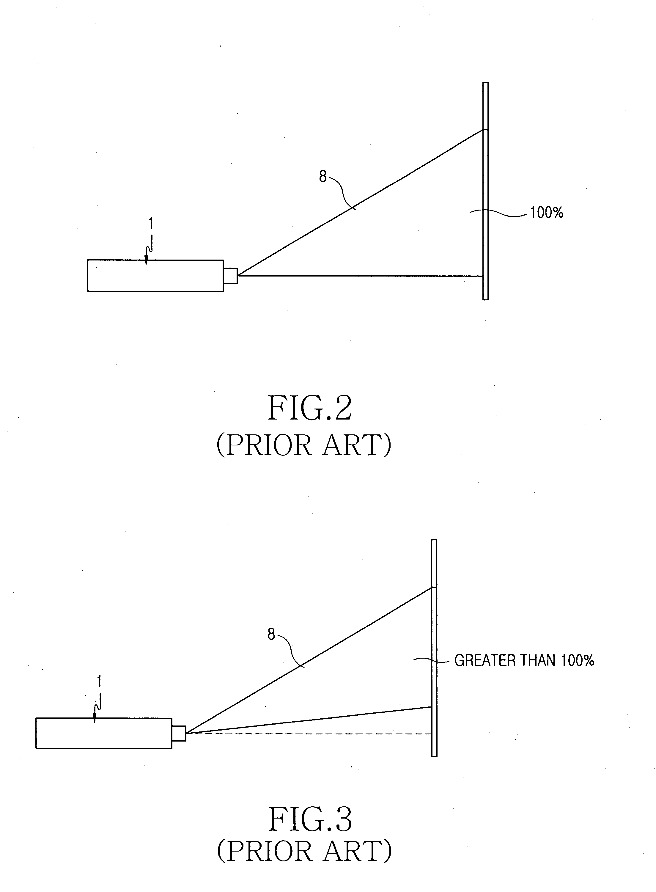
Also, when the mobile phone is used for various documents or personal entertainment, due to the fixed projection angle of the LCD projector, the size and the position of a desired projection screen vary depending upon the size of an image to be projected, whereby it is impossible to provide a clear image.

Method used


Image

  • Image offset adjustment apparatus for LCD projector and mobile phone having the same
  • Image offset adjustment apparatus for LCD projector and mobile phone having the same
  • Image offset adjustment apparatus for LCD projector and mobile phone having the same

Examples


first embodiment

[0037]Hereinafter, the present invention will be described with reference to the accompanying drawings. In the following description, the same component parts will be designated by the same reference numerals although they are shown in different drawings.

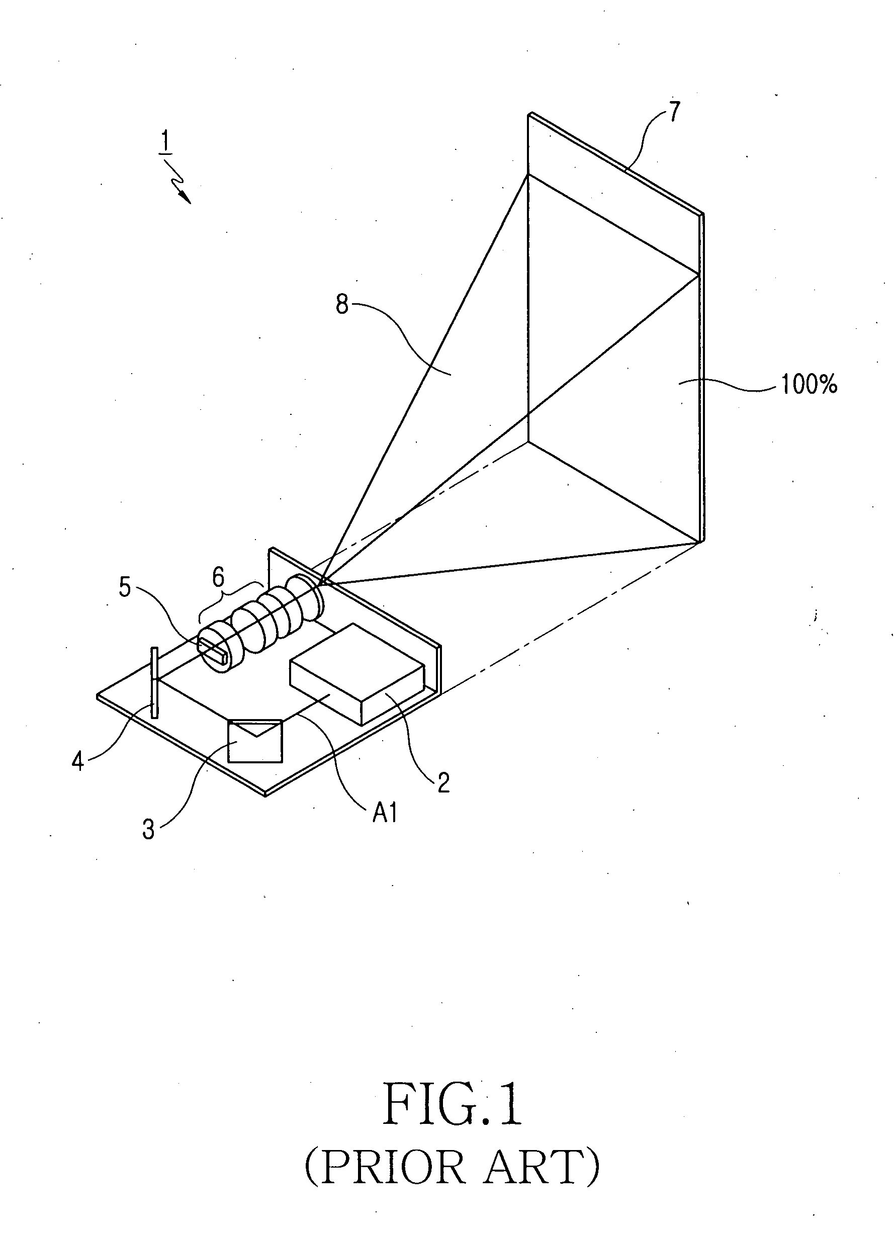
[0038]As shown in FIG. 4, an LCD projector comprises a light source 2 for emitting light A1, first and second mirrors 3 and 4 arranged in front of the light source 2 to reflect the light A1, LCDs 5 installed in front of the reflection mirrors 3 and 4 so that the reflected light A1 is transmitted to one of the LCDs 5 and that, when electric signals corresponding to a desired image drive liquid crystals and are selectively applied to a plurality of electrodes, alignment of the liquid crystals filled in the selected electrodes is changed to generate an image, and a screen (not shown) on which the image generated in one of the LCDs 5 is projected after being enlarged.

[0039]Referring to FIGS. 4 and 5, an image offset adjustment apparatus...

second embodiment

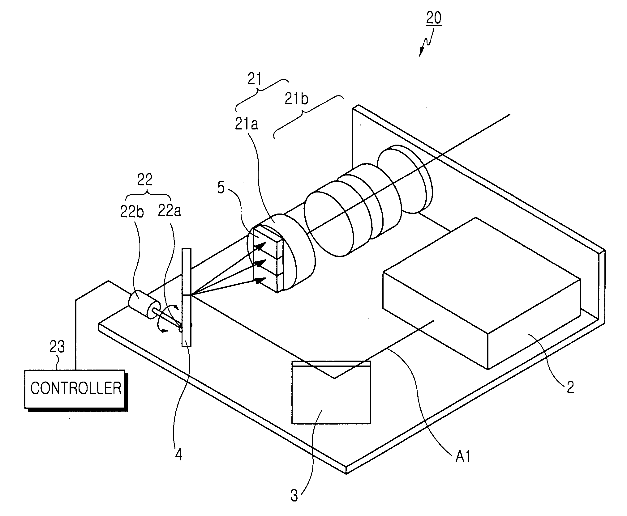
[0050]Hereafter, an image offset adjustment apparatus for an LCD projector in accordance with the present invention will be described with reference to FIGS. 6, 7 and 10.

[0051]Referring to FIGS. 6 and 7, the image offset adjustment apparatus 20 for an LCD projector comprises a first projection lens 21a which is located in the reflection direction of light A1 and which includes a plurality of LCDs 5 to have different image offsets, a rotation means 22, and a controller 23.

[0052]A projection lens section 21 is composed of first and second projection lenses 21a and 21b.

[0053]The light A1 emitted from a light source 2 is refracted by first and second mirrors 3 and 4 and is incident on one of the LCDs 5, and the image 8 generated in the corresponding LCD 5 is projected on the screen (not shown) through the projection lens section 21.

[0054]Due to the fact that the plurality of LCDs 5 having different image offsets are provided to the front surface of the first projection lens 21a, when a...

third embodiment

[0059]Hereafter, an image offset adjustment apparatus for an LCD projector in accordance with the present invention will be described with reference to FIGS. 8, 9 and 10.

[0060]Referring to FIGS. 8 and 9, the image offset adjustment apparatus 30 for an LCD projector comprises a projection lens 31 which is located in the refraction direction of light A1 and includes an LCD 5 provided on the front surface thereof, a moving means 32, and a controller 33.

[0061]The light A1 emitted from a light source 2 is reflected by first and second mirrors 3 and 4 and is incident on the LCD 5, and the image 8 generated by the LCD 5 is projected on the screen through the projection lens 31.

[0062]In this state, when a user wants to change the image offset, a signal is applied to the controller 33, and the controller 33 drives the moving means 32.

[0063]As shown in FIG. 9, due to the fact that the motor gear 32c of the motor 32b of the moving means 32 meshes with a rack gear 32a formed on the side surface...


PUM


Abstract

An image offset adjustment apparatus for an LCD projector which is constructed to enable the adjustment of an image offset. The LCD projector includes a light source for emitting light, mirrors, and an LCD installed in front of the mirrors so that an image generated in the LCD is enlarged and projected on a screen. The image offset adjustment apparatus includes a projection lens section including a plurality of projection lenses having their respective LCDs at different circumferential positions to have different image offsets; a lens housing for housing the respective projection lenses adjacent to one another in a circumferential direction; rotation means for rotating the lens housing; and a controller for controlling the rotation means so that the lens housing can be controllably rotated to select one of the projection lenses and one of the image offsets as desired by a user.

Description

PRIORITY[0001]This application claims a priority based on an application entitled “Image Offset Adjustment Apparatus For LCD Projector And Mobile Phone Having The Same” filed with the Korean Intellectual Property Office on May 8, 2006 and assigned with Serial No. 2006-41224, the contents of which are incorporated herein by reference.BACKGROUND OF THE INVENTION[0002]1. Field of the Invention[0003]The present invention relates to an image offset adjustment apparatus for an Liquid Crystal Display (LCD) projector which is constructed to enable the adjustment of an image offset in an LCD projector.[0004]2. Description of the Related Art[0005]Projectors that can project a small image on a large screen and that use a flat display having a slim configuration, instead of a Cathode Ray Tube (CRT) display limited screen size and a large system size, has drawn considerable attention. While a projector can adopt a CRT or an LCD as a display for a small image, an LCD projector using an LCD has be...

Claims


Application Information

Patent Timeline
Patent Type & Authority Applications(United States)
IPC IPC(8): G03B21/14
CPCG02B26/0816G02B26/0875H04N9/3141G03B21/28G03B33/16G03B5/00H04B1/40
Inventor PARK, SANG-CHANKIM, HYUN-SOOLEE, KI-TAELEE, KANG-HOONLEE, CHEONG-SUNSIM, DAE-HYUN
Owner SAMSUNG ELECTRONICS CO LTD
Learn More