Drive state shift control apparatus for hybrid vehicle

a technology of shifting control and hybrid vehicles, which is applied in the direction of engine-driven generator propulsion, electric propulsion mounting, transportation and packaging, etc., can solve the problems of shifting from ev to hev simultaneously, and not being able to achieve the driving force requested only by the motor-generator

Active Publication Date: 2007-11-08
NISSAN MOTOR CO LTD
View PDF8 Cites 69 Cited by
  • Summary
  • Abstract
  • Description
  • Claims
  • Application Information

AI Technical Summary

Benefits of technology

[0022]FIG. 11 is a shift diagram illustrating an example of modifying a shift line for fifth-to-fourth downshift in order to implement operations and advantageous effects according to an embodiment of the invention.

Problems solved by technology

This requires engine output, because it is impossible to attain the requested driving force only by the motor-generator.
The mode shift from EV to HEV will also occur when the charge of the battery for the motor-generator is insufficient, requiring engine output.
Further, in some cases, depressing the accelerator pedal causes a request to shift gears of the transmission simultaneously therewith.
Further, in some cases, releasing the accelerator pedal causes gear shifting of the transmission simultaneously therewith.

Method used


Image

  • Drive state shift control apparatus for hybrid vehicle
  • Drive state shift control apparatus for hybrid vehicle
  • Drive state shift control apparatus for hybrid vehicle

Examples


Embodiment Construction

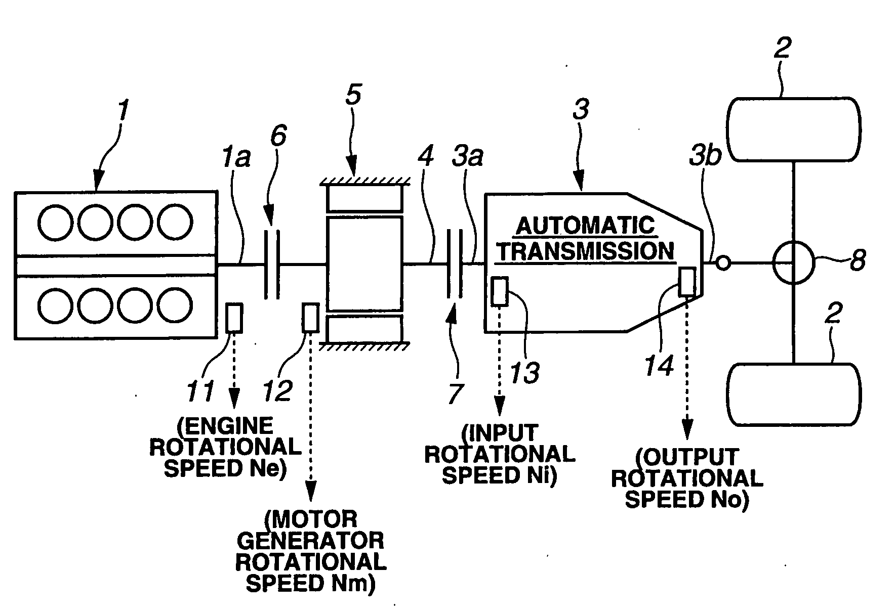
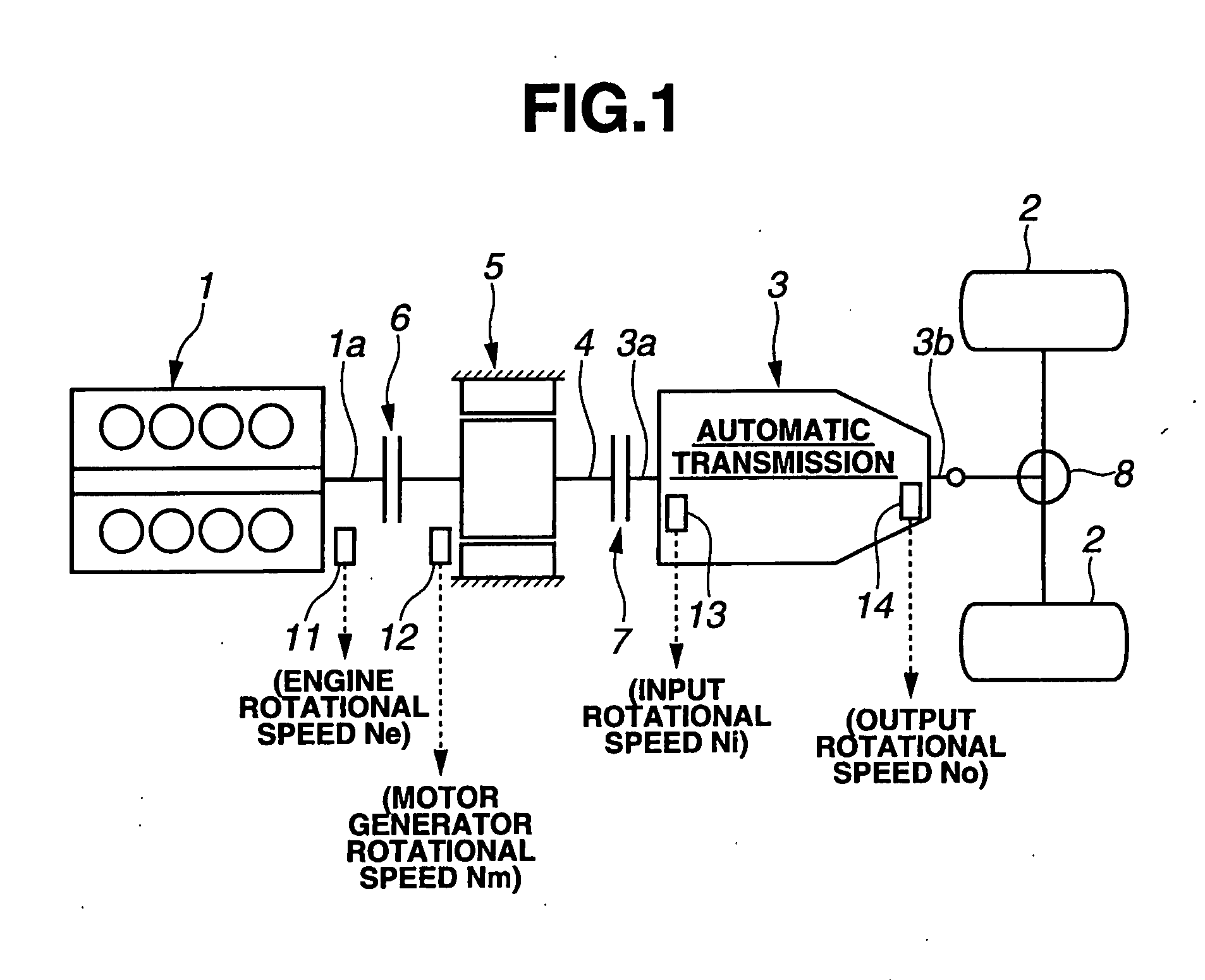
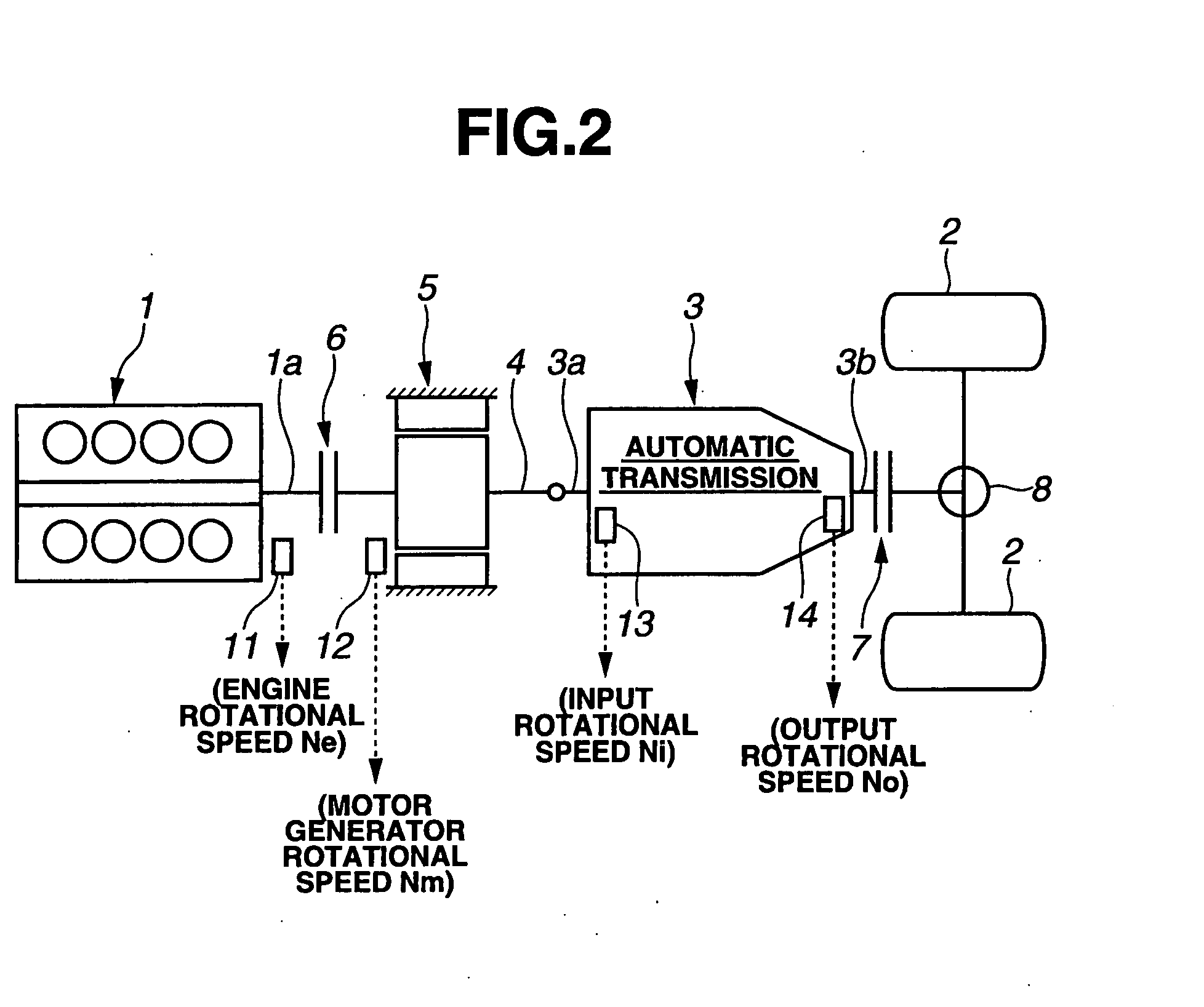
[0023]In order to satisfy the known requirements above, it has been suggested that, in the situation where the first clutch is engaged or disengaged and the engine is started or stopped in the mode shift, or where gear shifting is carried out in the mode shift, the second clutch which is provided in the driveline between the motor-generator and the driving wheels be disengaged. This may shorten the time intervals for starting or stopping the engine and performing the gear shift, and therefore effectively reduce torque fluctuations and their transmission to the driving wheels.

[0024]However, this countermeasure causes a problem of uncomfortable feel, especially when the accelerator pedal is pressed. This is because when the second clutch is disengaged, the driving wheels are completely separated from the power sources, causing an unintended drop in the driving force.

[0025]Further, in order to reduce shock and unintended driving force reduction, instead of the disengaging the second cl...


PUM


Abstract

A drive state shift control apparatus for a hybrid vehicle and a control method for a hybrid vehicle smoothly perform a shift in drive state in accordance with an operating state by a mode shift and a gear shift. When an accelerator operation causes a mode shift request and a gear shift request at substantially the same time, vehicle information including at least one of the vehicle speed and the engine load is used to determine the sequence of the shifts based on the competing interests of shock control and responsiveness.

Description

CROSS-REFERENCE TO RELATED APPLICATION[0001]This application claims priority from Japanese Patent Application Serial No. 2006-128436, filed May 2, 2006, which is incorporated herein in its entirety by reference.TECHNICAL FIELD[0002]The invention relates in general to a hybrid vehicle capable of running with power from a motor generator in addition to an engine.BACKGROUND[0003]Hybrid vehicles have an electric drive (EV) mode, in which the hybrid vehicle travels only by power from the motor-generator, and a hybrid drive (HEV) mode, in which the hybrid vehicle can travel by power from both the engine and the motor-generator. Hitherto, various types of hybrid driving devices used in hybrid vehicles have been proposed.[0004]Japanese Patent Application Publication No. 11-082260 shows one type of such a hybrid drive system. The hybrid drive system disclosed therein includes a motor-generator disposed between an engine and a transmission as a result of connecting an output shaft of the engi...

Claims


Application Information

Patent Timeline
Patent Type & Authority Applications(United States)
IPC IPC(8): B60K1/02B60K6/48B60L50/16B60W10/02B60W10/06B60W10/08B60W10/10B60W20/00
CPCB60K6/387B60K6/48B60K6/547B60L2240/443B60W10/02B60W10/08Y10T477/26B60W20/00B60W2510/0657B60W2520/10Y02T10/6221Y10S903/945Y10T477/23B60W10/11B60L15/2054B60L2240/421B60L2240/441B60L2240/486B60L2240/507B60L2270/145Y02T10/72B60L50/16Y02T10/62Y02T10/64Y02T10/7072B60K6/20B60W20/40Y02T10/70
Inventor TANISHIMA, KAORI
Owner NISSAN MOTOR CO LTD
Why Eureka
Try Eureka