Rod-loaded radiofrequency cavities and couplers

a technology which is applied in the field of radiofrequency cavity and coupler, can solve the problems of limited application and restrictive original form of pbg cavity

Inactive Publication Date: 2008-03-20
DULY RES
View PDF8 Cites 31 Cited by
  • Summary
  • Abstract
  • Description
  • Claims
  • Application Information

AI Technical Summary

Problems solved by technology

The PBG cavity in its original form is rather restrictive a...

Method used


Image

  • Rod-loaded radiofrequency cavities and couplers
  • Rod-loaded radiofrequency cavities and couplers
  • Rod-loaded radiofrequency cavities and couplers

Examples


Embodiment Construction

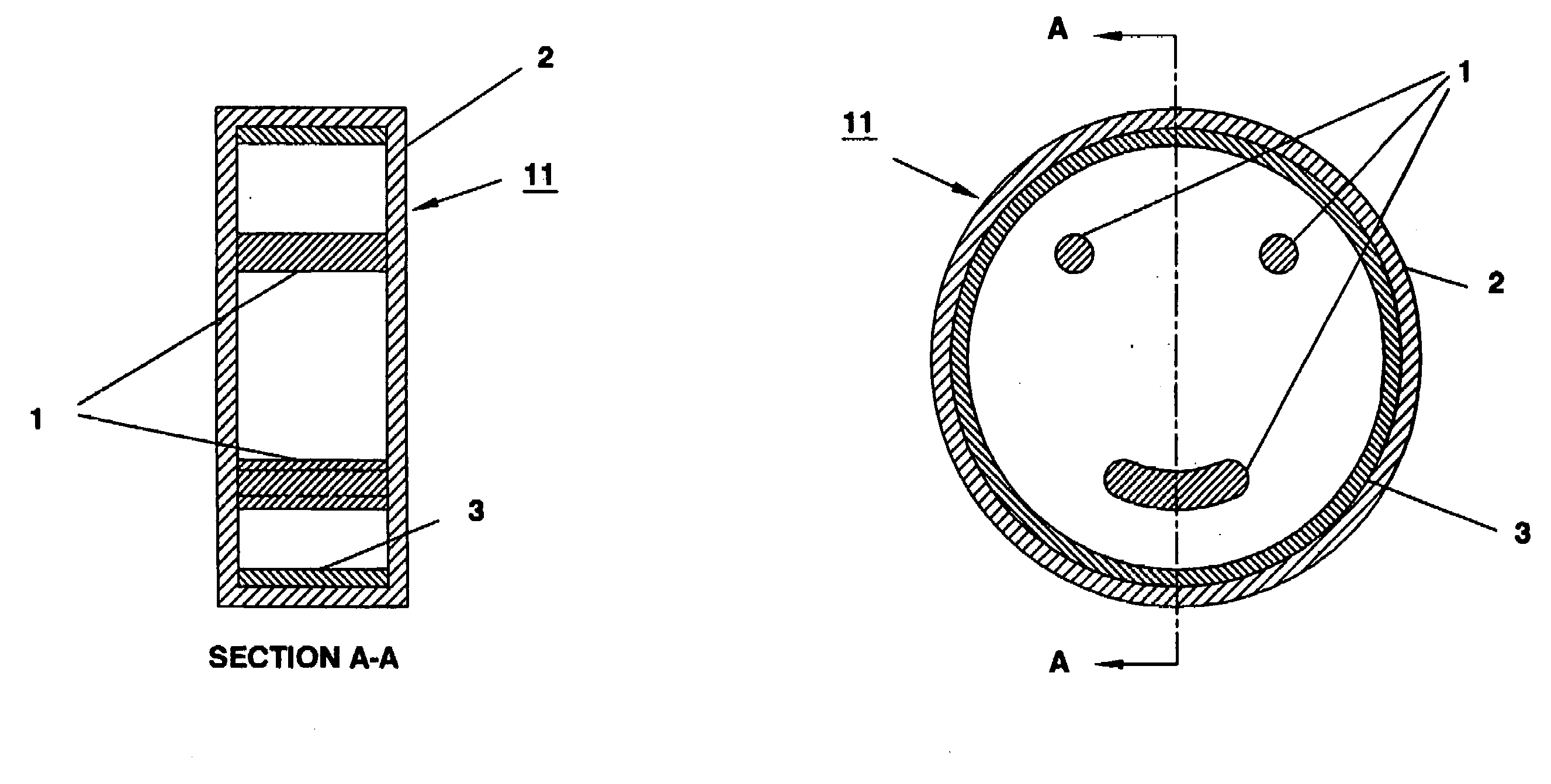
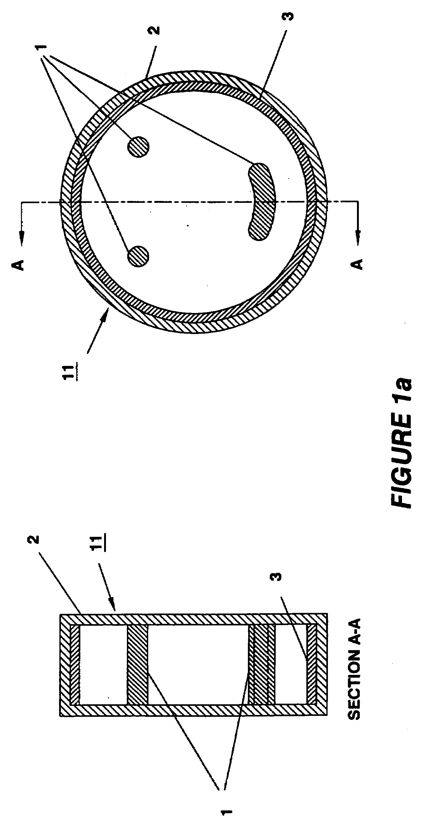
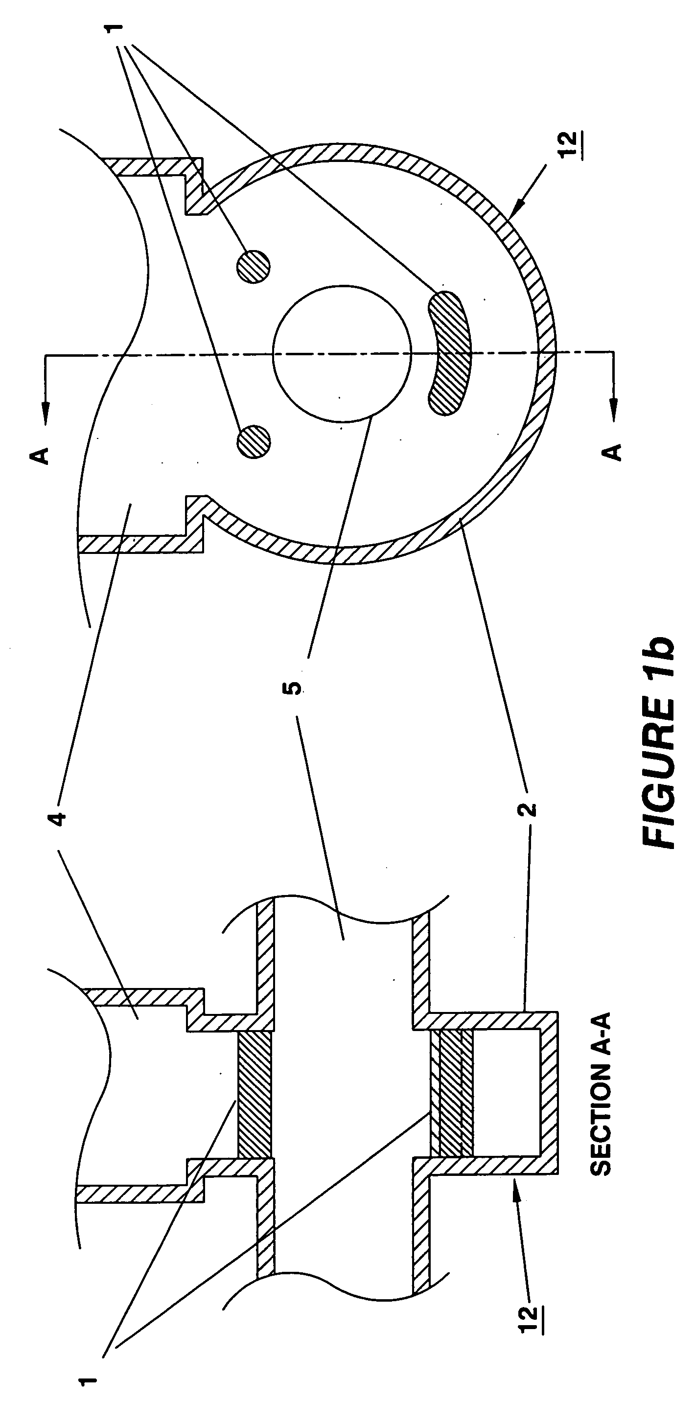
[0042]The electromagnetic field distribution in free space is modified in the presence of metallic or dielectric materials. In this invention we exploit this property by placing metallic and / or dielectric rods inside a cavity with metallic walls, in order to provide field patterns for achieving specific goals. The metal cavity may be lined with an absorptive material, or be loaded with external waveguide to decrease the Q factor for the operating mode or higher order modes.

[0043]FIGS. 1a and 1b illustrate the general principles of this invention. FIG. 1a shows two views of a rod-loaded cavity 11 wherein three rods 1 of arbitrary shapes are placed inside a closed copper cylindrical shell 2. The presence of the rods 1 causes the magnetic field around the rods 1 to be modified from that without the rods 1. The resonance frequency of a cavity without rods is also changed when metallic rods are placed inside the cavity. The materials, shapes, locations and the number of rods 1, as well a...


PUM


Abstract

This invention relates to radiofrequency (rf) cavities and couplers that comprise metallic or dielectric rods to provide specified concentration of field patterns for the operating modes in the interaction region, for applications in particle accelerators, pulsed rf power sources, amplifiers, mode converters and power couplers.

Description

GOVERNMENT RIGHTS[0001]This invention was made with government support under Grant No. DE-FG03-02ER83400 and Grant No. DE-FG02-03ER83845 awarded by the U.S. Energy Department. The government may have certain rights in the invention.BACKGROUND OF THE INVENTION[0002]1. Field of the Invention[0003]This invention relates generally to radiofrequency (rf) cavities and couplers for applications in particle accelerators, pulsed rf power sources, amplifiers, mode converters and power couplers. In particular the invention relates to rf cavities and couplers that comprise rods to provide specified concentration of field patterns for the operating modes in the interaction region.[0004]2. Description of Prior Art[0005]A radiofrequency (rf) cavity is a microwave resonator that stores electromagnetic field energy within its metallic or dielectric boundaries. The geometric structure and material of the cavity determine the rf frequency and the electromagnetic field pattern of the modes sustainable ...

Claims


Application Information

Patent Timeline
IPC IPC(8): H01P7/06
CPCH01P1/16H01P7/06H01P5/082H01P1/2005
Inventor YU, DAVID U.L.SMIRNOV, ALEXEI V.
Owner DULY RES
Why Eureka
Try Eureka